Eureka AIR delivers breakthrough ideas for toughest innovation challenges, trusted by R&D personnel around the world.

Floating fluid inlet for liquid containers and method of use thereof

Active Publication Date: 2012-07-26
BRODERICK WILLIAM
View PDF6 Cites 1 Cited by
  • Summary
  • Abstract
  • Description
  • Claims
  • Application Information

AI Technical Summary

Benefits of technology

[0030]Accordingly, a feature and advantage of the present invention is its ability to extract liquid from a vessel, drawing from near the top, but below the surface, of the liquid at all times.
[0031]Another feature and advantage of the present invention is its ability to avoid picking up sediment from the bottom of the vessel.
[0032]Still another feature and advantage of the present invention is its ability to readily disassembled for cleaning.
[0033]Yet another feature and advantage of the present invention is its reduced likelihood of becoming plugged by sediment.
[0034]Yet still another feature and advantage of the present invention is that it can be utilized with existing soda keg hardware.

Problems solved by technology

While the bottle is full, the aperture points upward (but below the liquid surface); however, when the bottle has very little liquid left in it, it does not support the float and the drawing aperture is positioned downward because of attached weighting means, thereby becoming more likely to pick up any sediments that exist on the bottom of the bottle.

Method used


Image

  • Floating fluid inlet for liquid containers and method of use thereof
  • Floating fluid inlet for liquid containers and method of use thereof
  • Floating fluid inlet for liquid containers and method of use thereof

Examples


Embodiment Construction

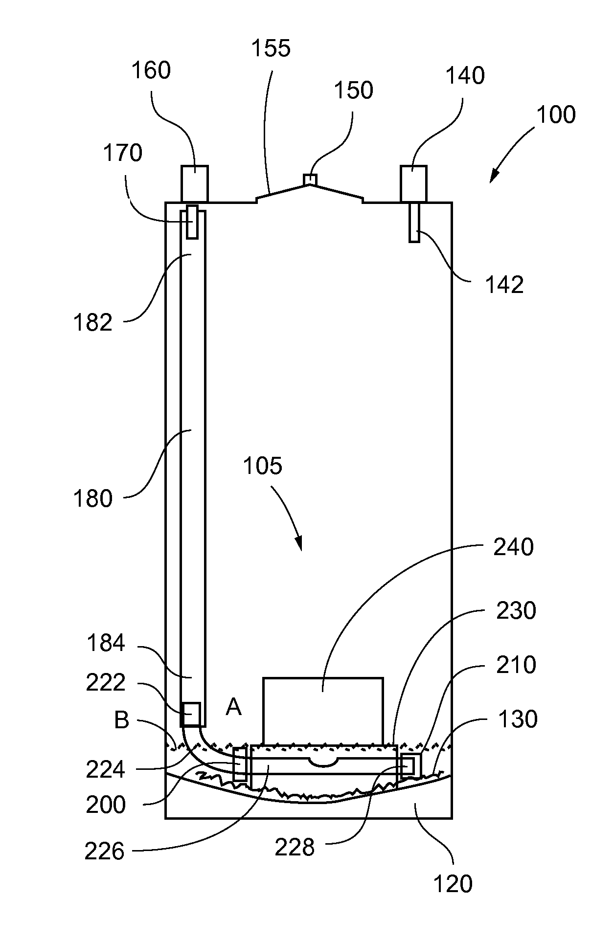
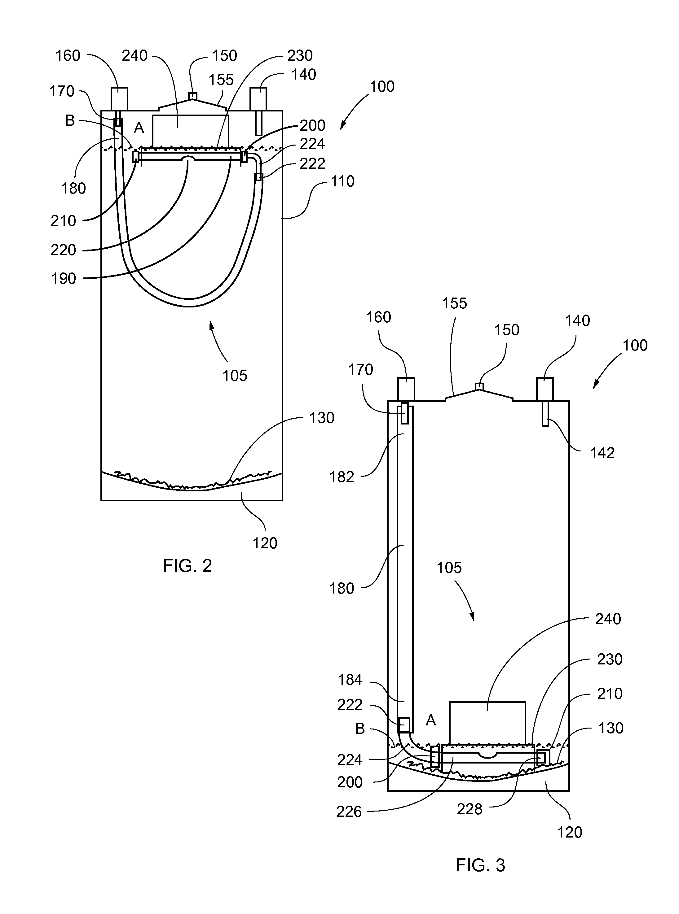
[0042]In describing the preferred embodiment of the present invention, as illustrated in FIGS. 1-5, specific terminology is employed for the sake of clarity. The invention, however, is not intended to be limited to the specific terminology so selected, and it is to be understood that each specific element includes all technical equivalents that operate in a similar manner to accomplish similar functions.

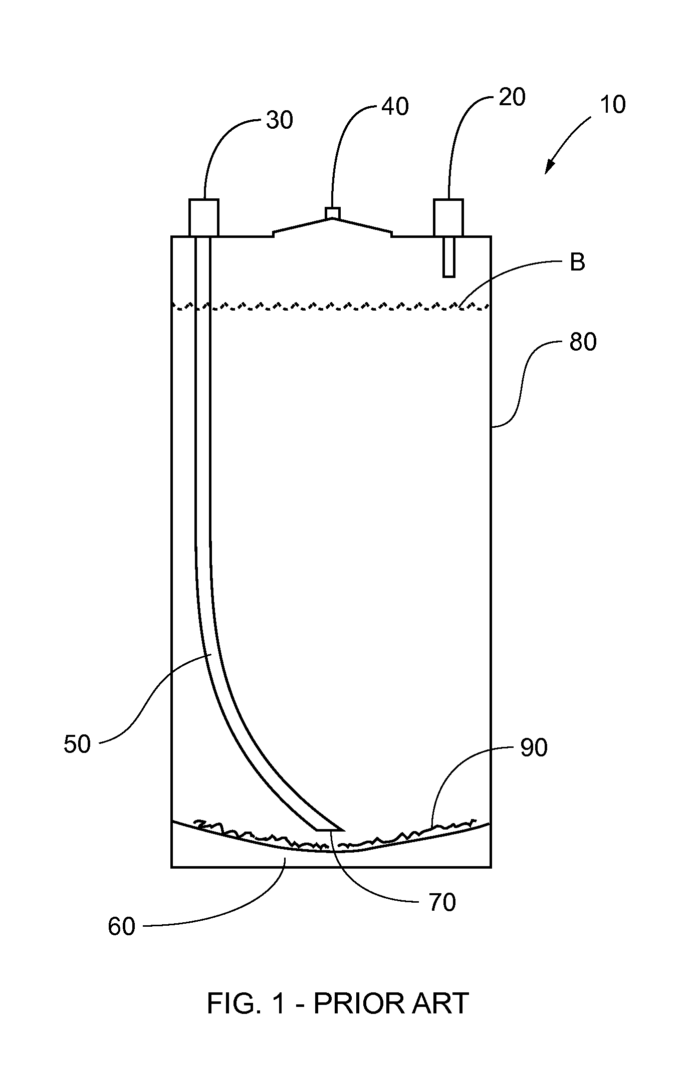
[0043]Referring now to FIG. 1, depicted therein is prior art beverage supply system 10, wherein prior art beverage supply system 10 comprises inlet port 20, outlet port 30, relief valve 40, pickup tube 50 having pickup tube opening 70 and soda keg 80 having bottom 60. Inlet port 20 is in fluid communication with a gas pressure source (not shown), such as, for exemplary purposes only, a carbon dioxide cylinder, thereby permitting pressurization of soda keg 80. Pickup tube 50 is secured to outlet port 30, wherein pickup tube 50 is utilized to remove beverage B from soda keg 80.

[0044]In...


PUM


Abstract

A floating fluid inlet that adjusts to the level of a beverage within a soda keg or similar container. The floating fluid inlet is constructed preferably of stainless steel and food grade plastic tubing. By rotating its inlet port aperture from downward facing when the soda keg is full of a beverage, to upward facing when the soda keg is nearly empty, the floating fluid inlet avoids picking up sediment from the bottom of the soda keg. The principal components are a tube that connects at its one end to the outlet port of a soda keg and at its other end to a pickup tube that is retained within a bracket to which is attached a float. The pickup tube has an aperture disposed in its sidewall for ingress of a beverage.

Description

CROSS-REFERENCE TO RELATED APPLICATIONS[0001]NoneFEDERALLY SPONSORED RESEARCH OR DEVELOPMENT[0002]NonePARTIES TO A JOINT RESEARCH AGREEMENT[0003]NoneREFERENCE TO A SEQUENCE LISTING[0004]NoneBACKGROUND OF THE INVENTION[0005]1. Technical Field of the Invention[0006]The present invention relates generally to floating intake ports for extracting liquid from containers, and more specifically to a floating inlet tube with an opening that avoids extracting sediment from the bottom of the container.[0007]2. Description of Related Art[0008]When extracting a liquid from a container, it is typical to provide a pickup tube that remains below the surface of the liquid so that air or other gas above the liquid surface does not enter the liquid that is being extracted.[0009]One previous device addresses this problem by teaching a nursing bottle having a nipple, a bottle portion, and a flexible dip tube adapted with a float near the drawing aperture thereof. The drawing aperture of the dip tube is ...

Claims


Application Information

Patent Timeline
IPC IPC(8): B67D7/78
CPCB67D1/0802
Inventor BRODERICK, WILLIAM
Owner BRODERICK WILLIAM
Why Eureka
Eureka Blog
Learn More