Relay with multiple contacts

Active Publication Date: 2012-07-26
SONG CHUAN PRECISION
View PDF4 Cites 6 Cited by
  • Summary
  • Abstract
  • Description
  • Claims
  • Application Information

AI Technical Summary

Benefits of technology

[0007]The main objective of the present invention is to provide an improved rel

Problems solved by technology

If a circuit has enough electric current and voltage to sustain an electric arc formed outside of an electrical device, the electric arc can cause damage to electric device such as melting of conductors, destruction of insulation, and fire.
It is difficult to apply the increased distance between two contacts / leads in the small-scale device for reducing the electric arcing.
And if the distance between two contacts / leads is increased, the conventional relay may cause the contact fault and the electric circuit of the relay may not be accurate.

Method used


Image

  • Relay with multiple contacts
  • Relay with multiple contacts
  • Relay with multiple contacts

Examples


Embodiment Construction

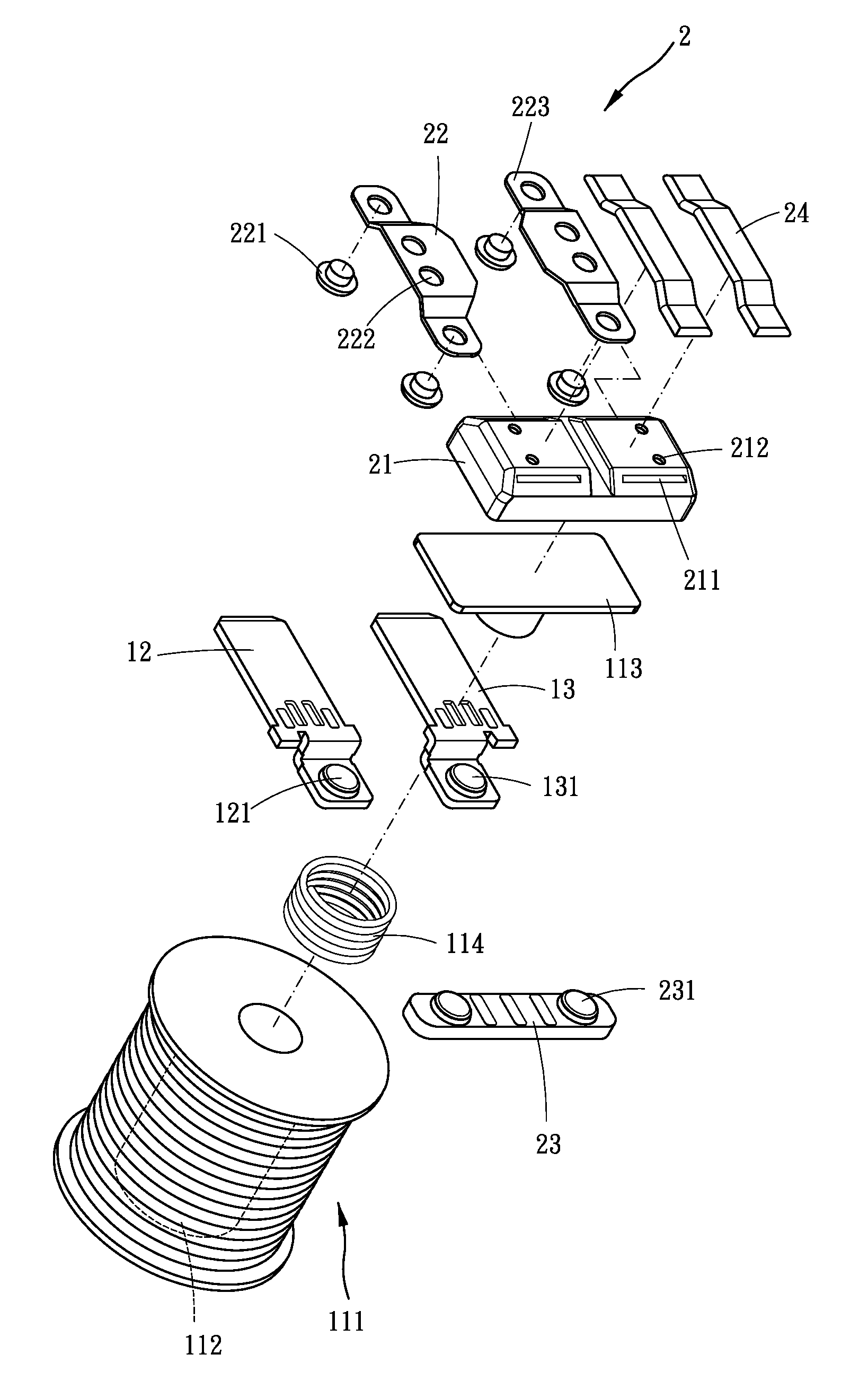
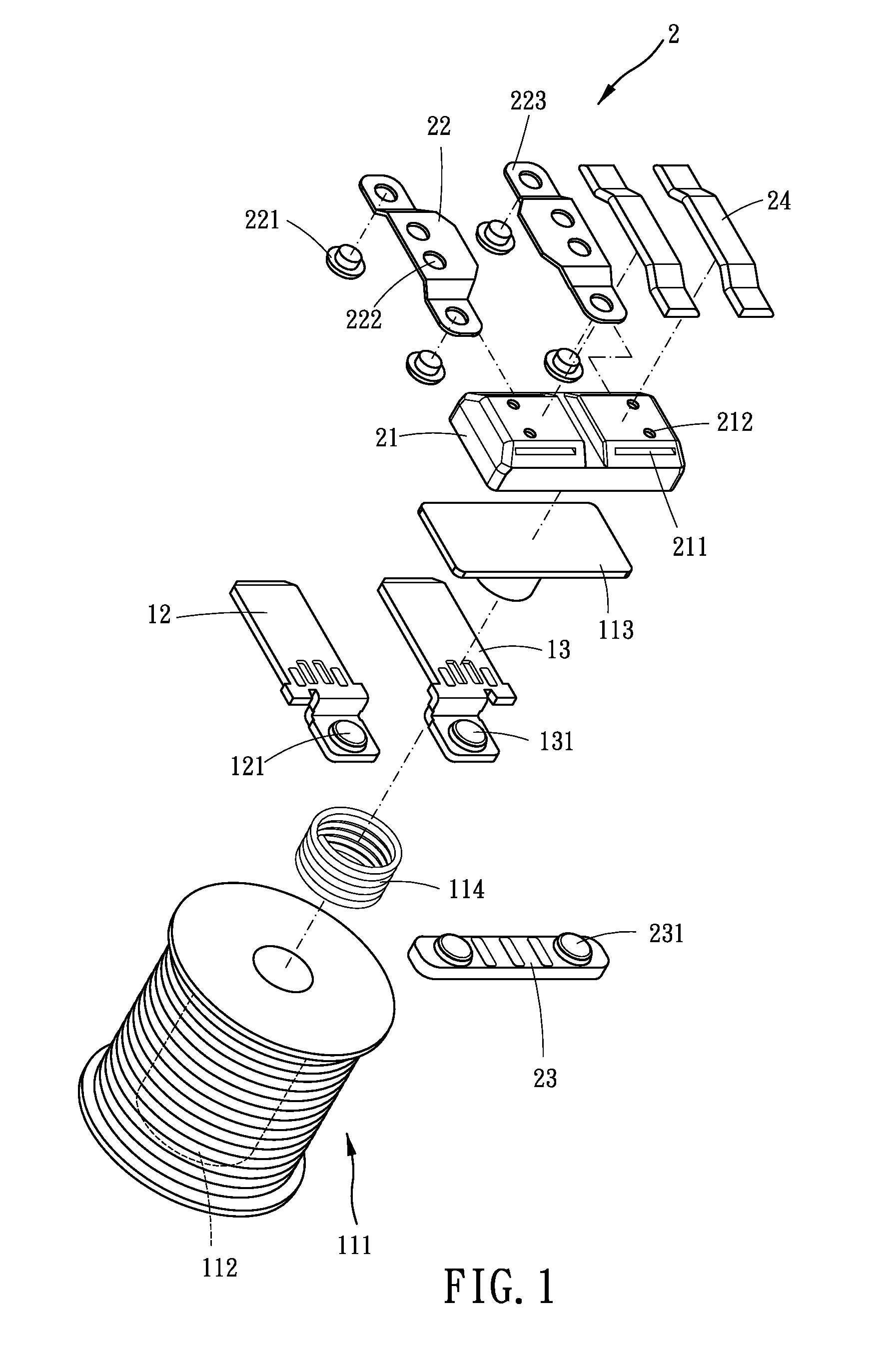
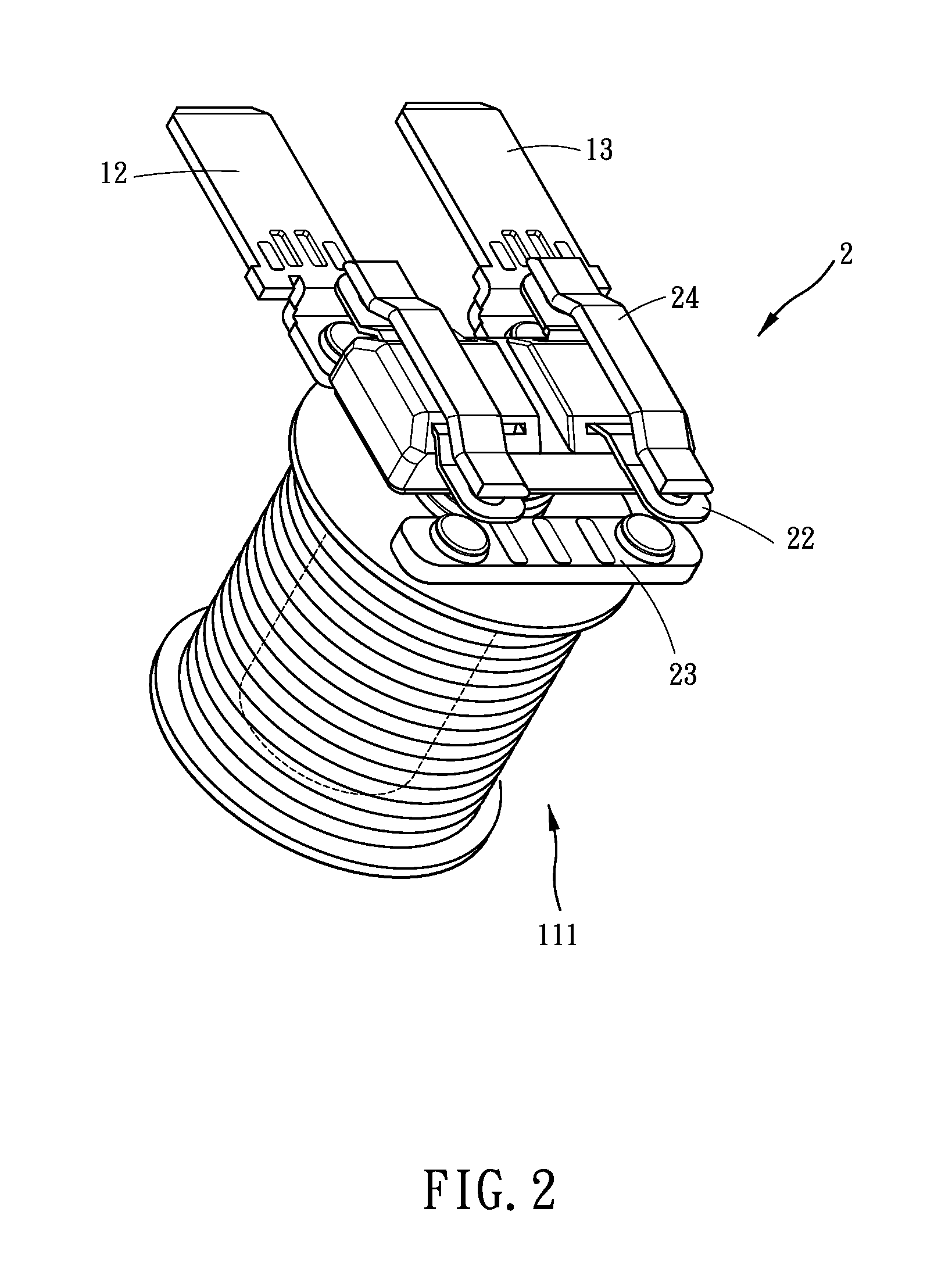
[0024]Referring to the drawings and initially to FIGS. 1-5, a relay with multiple contacts in accordance with a preferred embodiment of the present invention comprises a coil assembly 11, a contact assembly 2, a first conducting member 12, and a second conducting member 13. The coil assembly comprises a housing 1 for receiving the coil assembly 11, the contact assembly 2, the first conducting member 12, and the second conducting member 13. The coil assembly 11 has an iron core 112 received in the housing 1, a coil 111 sleeving on the iron core 112, a magnetic member 113 dispose above the coil 111, and a coil spring 114 disposed between the magnetic member 113 and the coil 111. The magnetic member 113 has a plate portion (not numbered) and a rod portion (not numbered) axially disposed on a bottom of the plate portion. The coil spring 114 sleeves on the rod portion of the magnetic member 113 and has two ends respectively abutting against the bottom of the plate portion and a top of th...


PUM


Abstract

A relay with multiple contacts includes a coil assembly and a contact assembly. The contact assembly includes at least one base having at least two slots defined therein and at least two bridge members respectively received in the at least two slots. Each bridge member has at least two terminal portions respectively formed thereon. Each terminal portion has a movable contact mounted thereon. At least one connector has at least two fixed contacts mounted thereon. Each fixed contact selectively connects with the corresponding movable contact. A first conducting member and a second conducting member are located between the coil assembly and the contact assembly. The first conducting member has at least one first fixed contact for selectively connecting with the corresponding movable contact. The second conducting member has at least one second fixed contact for selectively connecting with the corresponding movable contact.

Description

BACKGROUND OF THE INVENTION[0001]1. Field of the Invention[0002]The present invention relates to a relay with multiple contacts, and more particularly to a relay having multiple contacts disposed thereon for suppressing electric arc across two contacts.[0003]2. Description of Related Art[0004]A relay is an electrically operated switch for controlling a circuit by applying a low electric current. The most common types of relays used are electromechanical relays, reed relays, and solid state relays, etc. Generally, when electric current flows through the conventional relay, an electric arc is generated between two leads of the switch which are disposed in a distance. If a circuit has enough electric current and voltage to sustain an electric arc formed outside of an electrical device, the electric arc can cause damage to electric device such as melting of conductors, destruction of insulation, and fire. In order to eliminating the electric arcing, capacitors in parallel and resistor, ...

Claims


Application Information

Patent Timeline
IPC IPC(8): H01H1/58
CPCH01H50/546H01H9/40
Inventor WU, SUNG JEN
Owner SONG CHUAN PRECISION
Why Eureka
Try Eureka