

Rotor assembly for a rotorcraft
- Summary
- Abstract
- Description
- Claims
- Application Information
AI Technical Summary
Benefits of technology
Problems solved by technology
Method used
Image

Examples
first embodiment
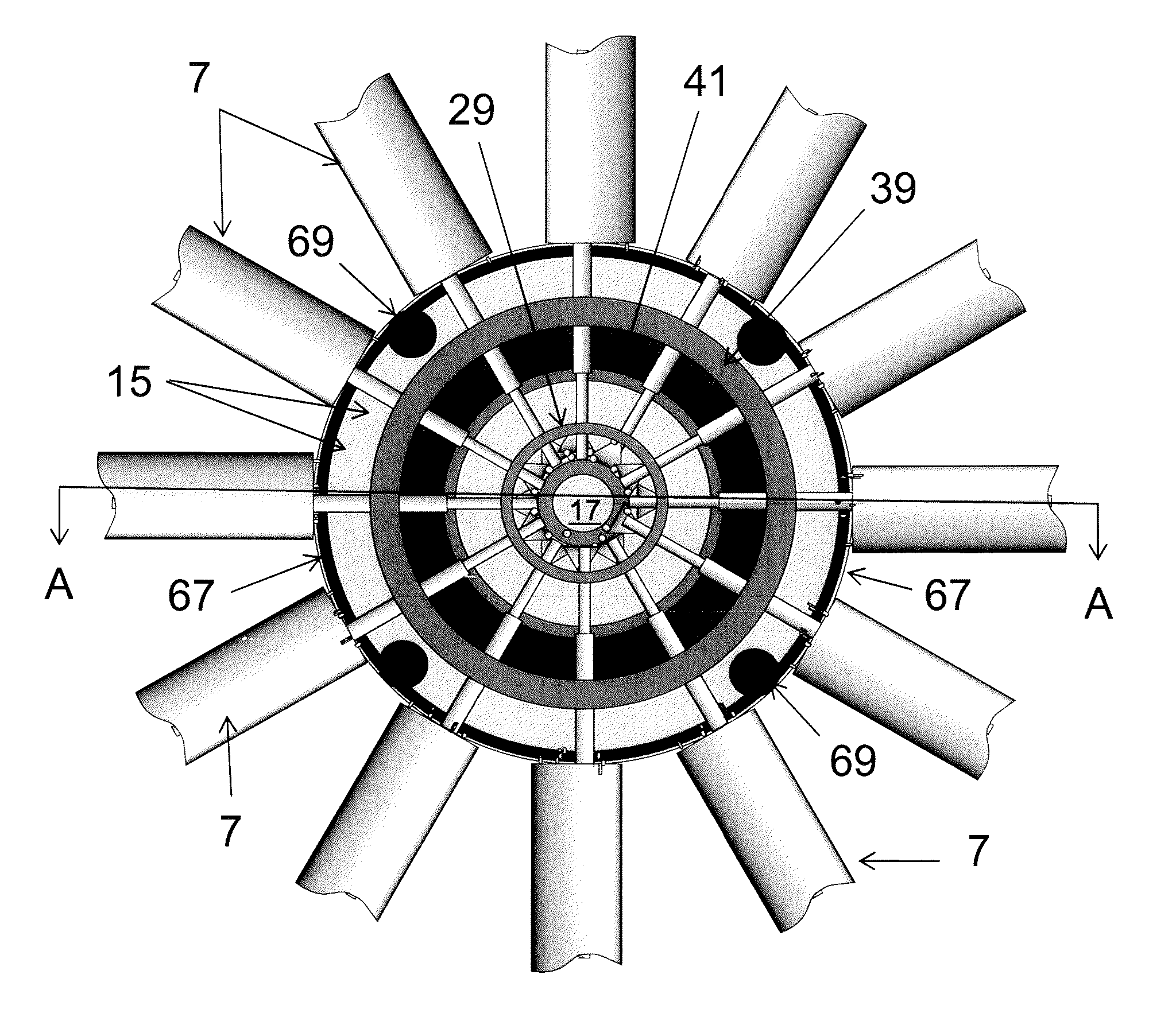
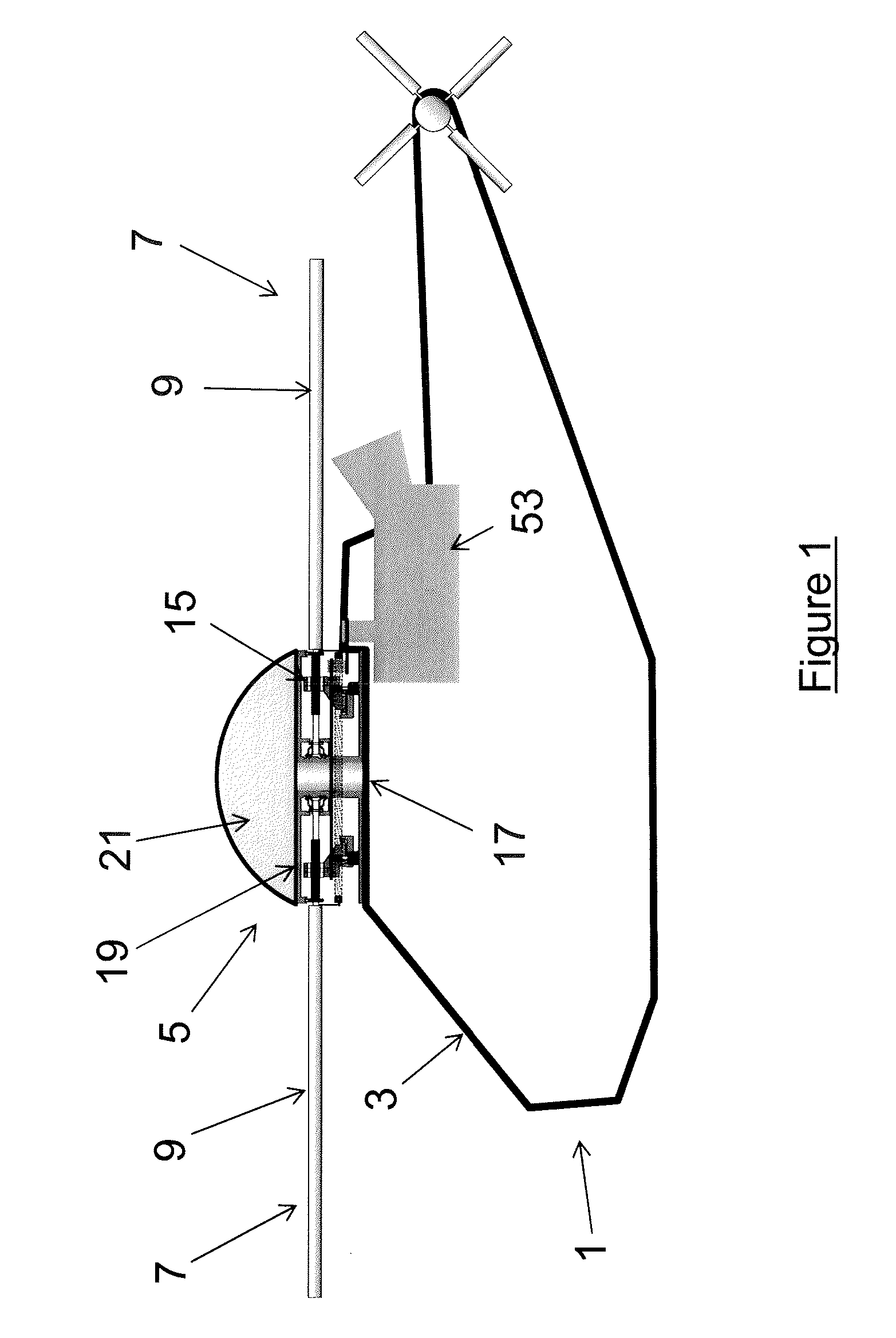
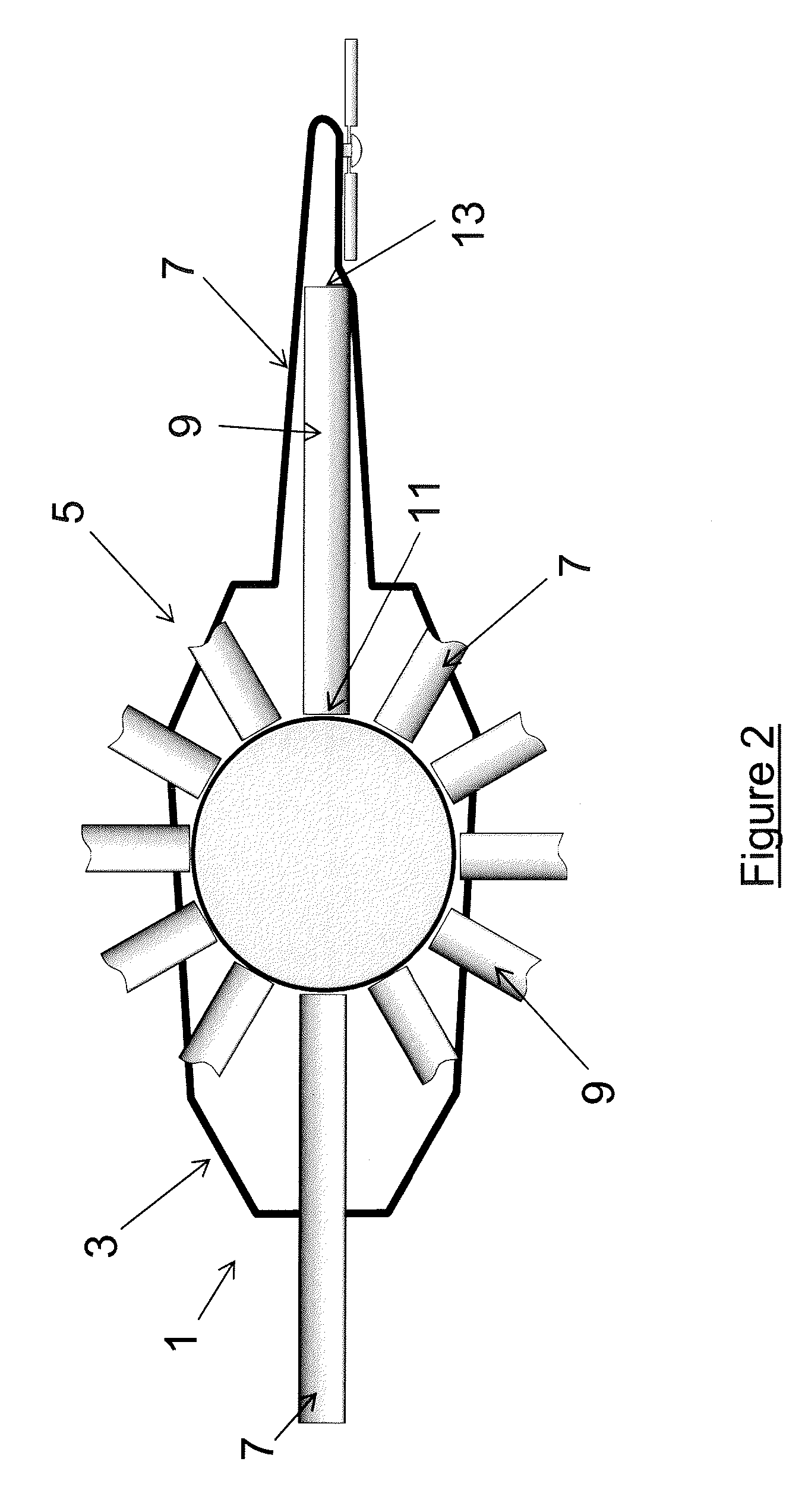
[0061]According to the invention, a helicopter 1 comprises a fuselage 3 and a rotor assembly 5 mounted on the top of the fuselage 3. The rotor assembly carries twelve rotors 7, each rotor comprising a 3 m long blade 9 having an aerofoil section (the full length of only the forward and aft rotors is shown in FIG. 2, only the inner region of the other rotors being shown). The blade 9 extends from a root 11 to a tip 13. For the sake of clarity, each rotor blade 9 is shown having a uniform chord and zero twist / washout. In practice, the chord and twist of the blade 9 vary along the length of the blade as is well known in the art. A 1 m long shaft 15, aligned with the centre of lift of the blade 9, extends from the root 11 of the blade to a hub 17. The rotor assembly 5 comprises a disc-shaped cover portion 19 which is fixedly attached to the top of the hub 17. The cover portion extends outwardly to the root 11 of the rotor blades 7. A dome-shaped cowling 21 is attached to the top of the c...
second embodiment
[0080]FIGS. 11 and 12 show a second embodiment of the invention. the invention is generally the same as the first embodiment except for the differences described below. The equivalent features are numbered with the same reference numerals except for a prefix of 1, or 10 as appropriate. According to the second embodiment, the rotor assembly comprises a flap controller and a pitch controller. The pitch controller is arranged in similar manner to that in the first embodiment of the invention, except that the pitch guide ring 167 is located above the blade and the actuators 169 are not attached to the fuselage. Instead, the actuators 169 are mounted on a second guide ring 177 which is part of a flap controller.
[0081]The flap controller comprises the flap guide ring 177 attached to the flap actuators 179. A linkage 181 links the flap guide ring 177 to the shaft of each rotor at a position close to the root 111 of the blade 109, and radially outward of a flap hinge 183. The linkage 181 is...
third embodiment
[0088]In a further embodiment, that is a variation on the third embodiment, the rotor assembly further comprises a filtered air duct for ducting air flow into the region within the plates. A positive pressure is therefore established in the chamber that further reduces the exposure of moving parts to the outside environment.
[0089]According to another embodiment (not shown), the rotor assembly comprises two perpendicular actuators for moving the drive ring. At maximum extension the left / right actuator positions the drive ring as described with reference to the first embodiment. At maximum contraction, the left / right actuator positions the drive ring over the far left-hand side of the assembly. A front / back actuator is operable to position the drive ring forward or aft of the hub centre. Of course, a combination of front / back and left / right positioning on the ring is also possible. It will be appreciated that a lateral movement is any movement in any direction within the horizontal pl...
PUM
 Abstract
Description
Claims
Application Information