

Extrusion Process For Proppant Production
a technology of extrusion process and proppant, which is applied in the direction of ceramic extrusion die, sealing/packing, borehole/well accessories, etc., can solve the problems of low cost of sand, high cost of sand, and extreme density of conventional proppants
- Summary
- Abstract
- Description
- Claims
- Application Information
AI Technical Summary
Benefits of technology
Problems solved by technology
Method used
Image

Examples
example 1 (
Theoretical Example)
[0247]A ceramic powder mixture of aluminosilicate glass and alumina with a mean particle size of approximately 1.50±0.05 μm is charged into the muller of the extruder. To the powder is added 50.0±0.5 g of oleic acid as an extrusion lubricant. The resulting mixture is mulled for approximately 5 minutes, after which time 250±0.5 g of methyl cellulose is added to act as a binder. Mulling of the powder / lubricant / binder is continued for 10 minutes, after which time a quantity of water is added to wet out the powder and form a paste suitable for extrusion. The quantity of water added is typically 500±1 g. The paste is mulled for an additional 20 minutes under vacuum to de-gas the paste prior to extrusion. The paste is moved from the reservoir to the extrusion die by way of a twin screw feeder. The extrusion die has multiple circular apertures of approximately 915 μm. The paste extrudes from the die set and forms a continuous extrudate of circular cross-section with a m...
example 2 (
Theoretical Example)
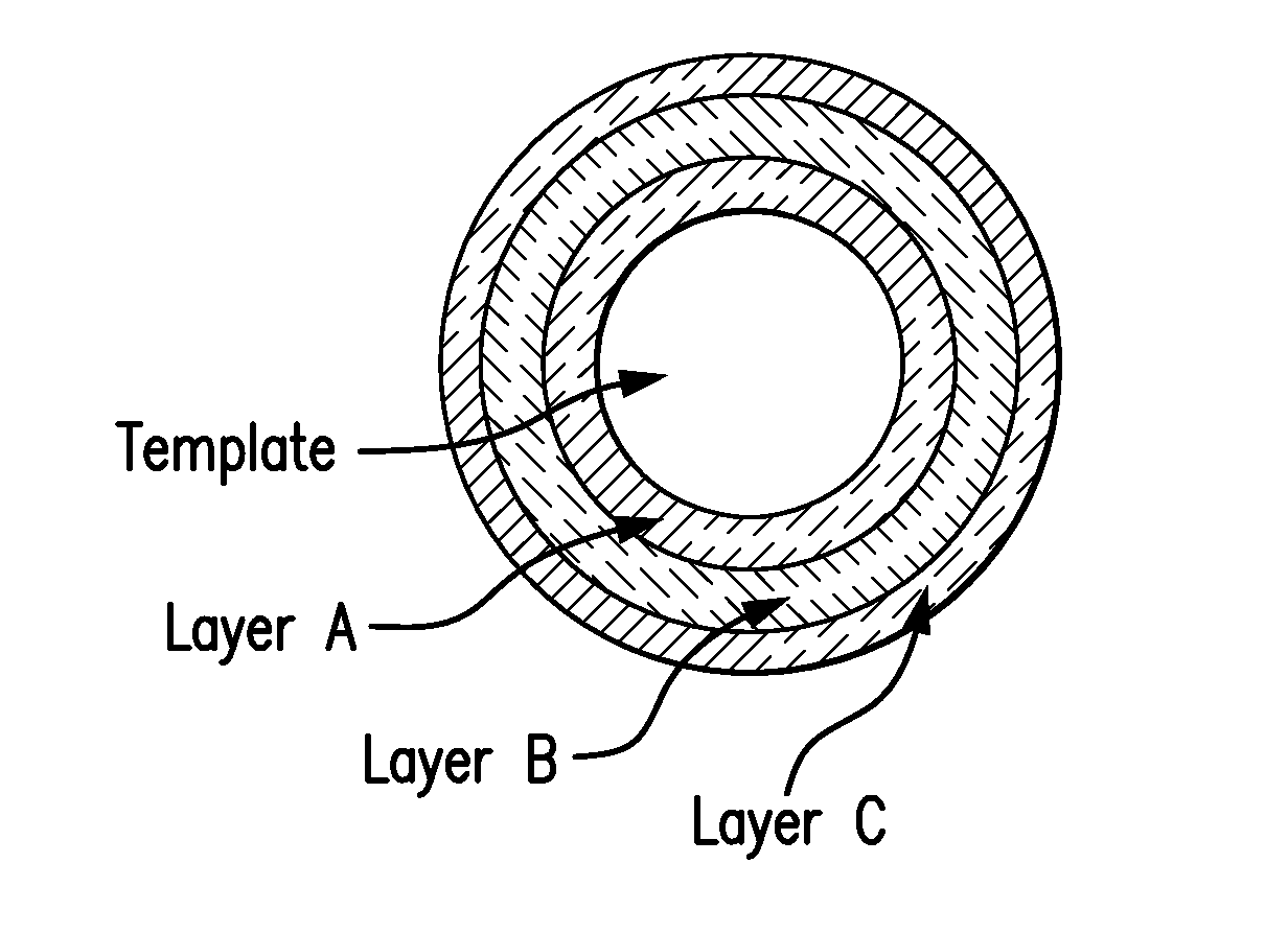
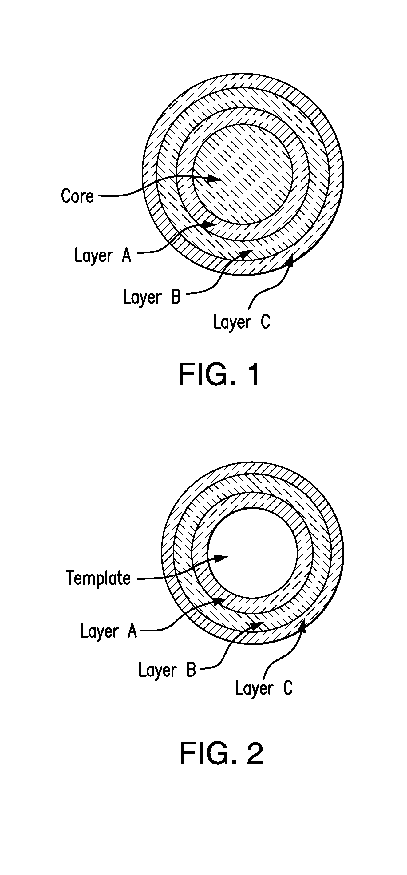
[0248]The paste of the same composition (and additives) as in Example 1 is prepared and is extruded through a modified die. The modified die has circular apertures with a circular mandrel of 250 μm diameter centered in each aperture of the die. The extrudate thus formed is tubular in nature with an inside diameter of approximately 250 μm and an outside diameter of approximately 915 μm. The resulting tubular extrudate is cut into lengths of 915 μm by way of a crimping action using a tool with a conical profile. The resulting crimped extrudate sections are processed in the Eirich mixer and sintered as in Example 1, yielding hollow proppant spheres of approximately 750 μm (US Mesh #20) diameter.
example 3 (
Theoretical Example)
[0249]A ceramic polymer mixture of composition 80 vol % ceramic powder mixture with the composition of Example 1 and 20 vol % low density polyethylene is mixed in the muller for 10 minutes. The resulting ceramic—polymer mixture is heated to approximately 115° C. and mulling continued for approximately 15 minutes to melt and mix the two components together into a homogenous mix. The resulting ceramic—polymer blend is extruded through the same die as used in Example 1 and the extrudate is maintained at a temperature of approximately 75° C. and cut into lengths of 915 μm using a planar cutting blade. The cut extrudates are placed into a heated forging die of two pieces with hemispherical cavities. The forging die is maintained at approximately 100° C. The extrudates are oriented such that the axial direction of the cylindrical extrudates are perpendicular to the face of the forging die. The cylindrical extrudates are forged to spheres with a diameter of 915 μm. Heat...
PUM
| Property | Measurement | Unit |
|---|---|---|
| Temperature | aaaaa | aaaaa |
| Force | aaaaa | aaaaa |
| Pressure | aaaaa | aaaaa |
Abstract
Description
Claims
Application Information