Reciprocating power tool

Active Publication Date: 2012-08-02
MAKITA CORP
View PDF18 Cites 40 Cited by
  • Summary
  • Abstract
  • Description
  • Claims
  • Application Information

AI Technical Summary

Benefits of technology

[0006]Accordingly, it is an object of the invention to reduce vibration by a counter weight that

Problems solved by technology

However, vibration is caused by collision when the counter weight reverses its

Method used


Image

  • Reciprocating power tool
  • Reciprocating power tool
  • Reciprocating power tool

Examples


first embodiment

of the Invention

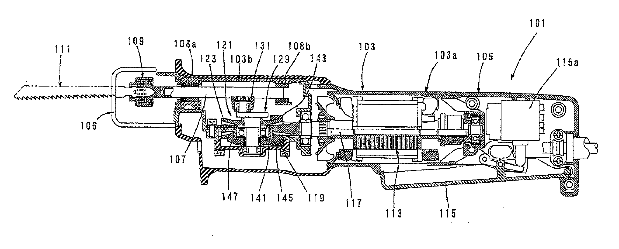
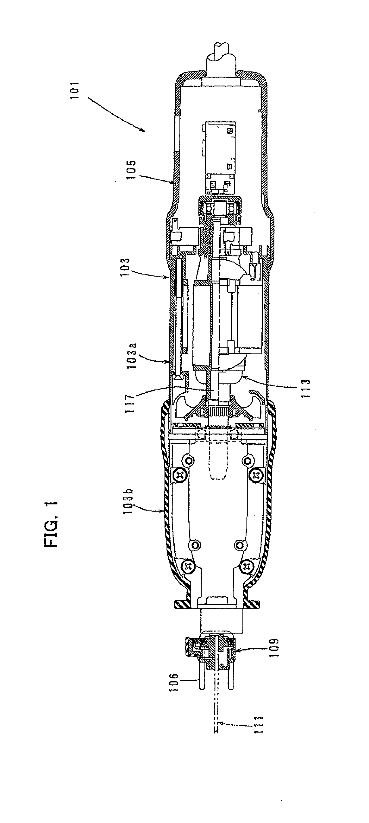
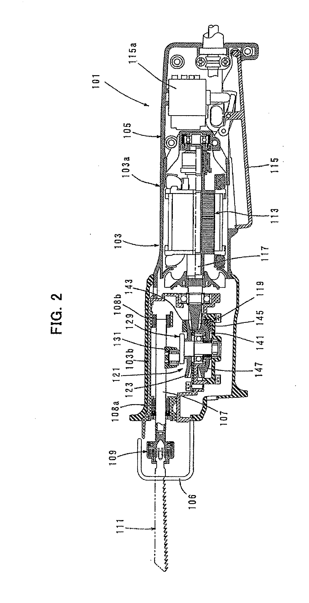
[0026]A representative embodiment of the invention is now described with reference to FIGS. 1 to 5. In this embodiment, a reciprocating saw 101 is explained as a representative example of a reciprocating power tool according to the invention. FIG. 1 is a sectional plan view showing the entire structure of the reciprocating saw 101 according to this embodiment. FIGS. 2 and 3 are longitudinal sectional views showing the entire structure of the reciprocating saw 101. In FIG. 2, a slider 107 is shown located at the end of forward movement (to the left as viewed in FIG. 2), and in FIG. 3, the slider 107 is shown located at the end of rearward movement (to the right as viewed in FIG. 3). FIG. 4 is an enlarged sectional view showing an essential part of the reciprocating saw 101 according to the invention and FIG. 5 is a view illustrating movement of counter weights 143, 145.

[0027]As shown in FIGS. 1 to 3, the reciprocating saw 101 according to this embodiment mainly includ...

second embodiment

of the Invention

[0042]A second embodiment of the invention is now explained with reference to FIGS. 6 to 9. FIG. 6 is a longitudinal sectional view showing an entire structure of the reciprocating saw 101 according to the second embodiment, and FIG. 7 is a sectional view showing an essential part of the reciprocating saw 101. FIG. 8 is a plan view showing a mounting structure of a driving-side counter weight 143, and FIG. 9 is a sectional view taken along line A-A in FIG. 8. This embodiment is a modification to the counter weight mechanism 141 for reducing vibration, and in the other points, it has the same construction as the above-described first embodiment. Therefore, components which are substantially identical to those in the first embodiment are given like numerals as in the first embodiment and are not described or only briefly described.

[0043]In this embodiment, the driving bevel gear 123 is mounted onto the lower region of the crank shaft 129a such that it rotates together ...

third embodiment

of the Invention

[0056]The reciprocating saw 101 according to a third embodiment of the invention is now explained with reference to FIGS. 11 and 12. FIG. 11 is a longitudinal sectional view showing an entire structure of the reciprocating saw 101 according to the third embodiment, and FIG. 12 is a sectional view showing an essential part of the reciprocating saw 101. The reciprocating saw 101 according to this embodiment is constructed such that the slider 107 which holds the blade 111 is caused to perform not only linear reciprocating motion in the back-and-forth direction but also swinging motion in a vertical direction transverse to this linear reciprocating motion. Specifically, the blade 111 is caused to move in an ellipse or perform orbital motion by a combination of linear reciprocating motion and swinging motion.

[0057]An orbital mechanism which causes the slider 107 holding the blade 111 to perform orbital motion mainly includes the motion converting mechanism 121 which is f...


PUM

PropertyMeasurementUnit
Weightaaaaaaaaaa
Ratioaaaaaaaaaa
Distanceaaaaaaaaaa

Abstract

It is an object of the invention to provide a technique for reducing vibration by counter weights which smoothly operate without linearly reciprocating, in a reciprocating power tool.
The reciprocating power tool has first and second bevel gears 123, 147 which are opposed to each other on either side of a pinion 119 and rotationally driven in opposite directions at the same reduction ratio by the pinion 119. Further, the reciprocating power tool has a slider 107 which is caused to linearly reciprocate in a longitudinal direction of a tool bit 111 by a crank 129. The first and second bevel gears 123, 147 are provided with first and second counter weights 143, 145 in positions displaced from their rotation axes, respectively. When the first counter weight 143 and the second counter weight 145 revolve, components of the revolving motion in the longitudinal direction of the tool bit oppositely move with respect to linear motion of the slider 107, and the first counter weight 143 and the second counter weight 145 move in the same phase in the longitudinal direction of the tool bit 111 and are disposed on opposite sides of the rotation axis and at the same distance from the rotation axis in a direction transverse to the longitudinal direction of the tool bit 111.

Description

BACKGROUND OF THE INVENTION[0001]1. Field of the Invention[0002]The invention relates to a vibration reducing technique for a reciprocating power tool, such as a reciprocating saw and a jig saw, which performs a cutting operation on a workpiece by reciprocating a tool bit.[0003]2. Description of the Related Art[0004]Japanese non-examined laid-open Patent Publication No. 2005-14111 discloses a reciprocating saw in which, when a slider with a tool bit reciprocates via a crank by a motor in order to perform a cutting operation by the tool bit, a counter weight reciprocates to opposite to a slider. Specifically, the counter weight is caused to linearly move in a direction opposite to the slider, so that vibration caused by reciprocating motion of the slider is reduced.[0005]According to the vibration reducing method for the reciprocating saw in which the counter weight reciprocates in a phase opposite to linear reciprocating motion of the slider, the momenta of the slider and the counte...

Claims


Application Information

Patent Timeline
IPC IPC(8): B23D49/16B27B11/00
CPCB23D51/16B23D49/165
Inventor AOKI, YONOSUKEHIRABAYASHI, SHINJI
Owner MAKITA CORP
Why Eureka
Try Eureka