
Breech Device

a breech device and a technology for handguns, applied in the field of breech devices, can solve the problems of high machining costs in the manufacturing process, and the breech device accounts for a high percentage of the total production cost of a handgun

Active Publication Date: 2012-08-02
WALTHER & CO AG
View PDF16 Cites 3 Cited by
  • Summary
  • Abstract
  • Description
  • Claims
  • Application Information

AI Technical Summary

Benefits of technology

[0004]It is therefore an object of the invention to provide a breech device involving production costs that are lower than those of known breech devices but displaying the same quality and reliability.
[0007]In the breech device of the invention, the combination of features, namely the provision of the main functional region in the form of a main functional element that forms a compact unit and is capable of being releasably anchored securely by means of a fixing device in a pre-defined position in an internal profile of the central recess of the breech device, results in a breech device that can be assembled securely from at least two cheaply and separately producible components to form a robust unit. The two components can be made of different materials, if desired, and use may be made of plastics materials, if appropriate. Usually, the main functional element has a morphologically structured functional shape, which can be created more simply and at less expense when produced as a separate component rather than as part of an internal structure of a breech block.
[0016]Accordingly, a rear end face of a breech block is configured to be open for inserting the main functional element in order to make it possible to subsequently insert the main functional element into the breech blank.

Problems solved by technology

However, the known breech devices suffer from the disadvantage that the production of an internal functional surface with at least one morphologically structured internal functional guiding surface or, more particularly, a number of different morphologically structured internal functional guiding surfaces, necessitates high machining costs in the manufacturing process, as a result of which the production of a breech device accounts for a high percentage of the total production costs of a handgun.

Method used


Image

  • Breech Device
  • Breech Device
  • Breech Device

Examples


Embodiment Construction

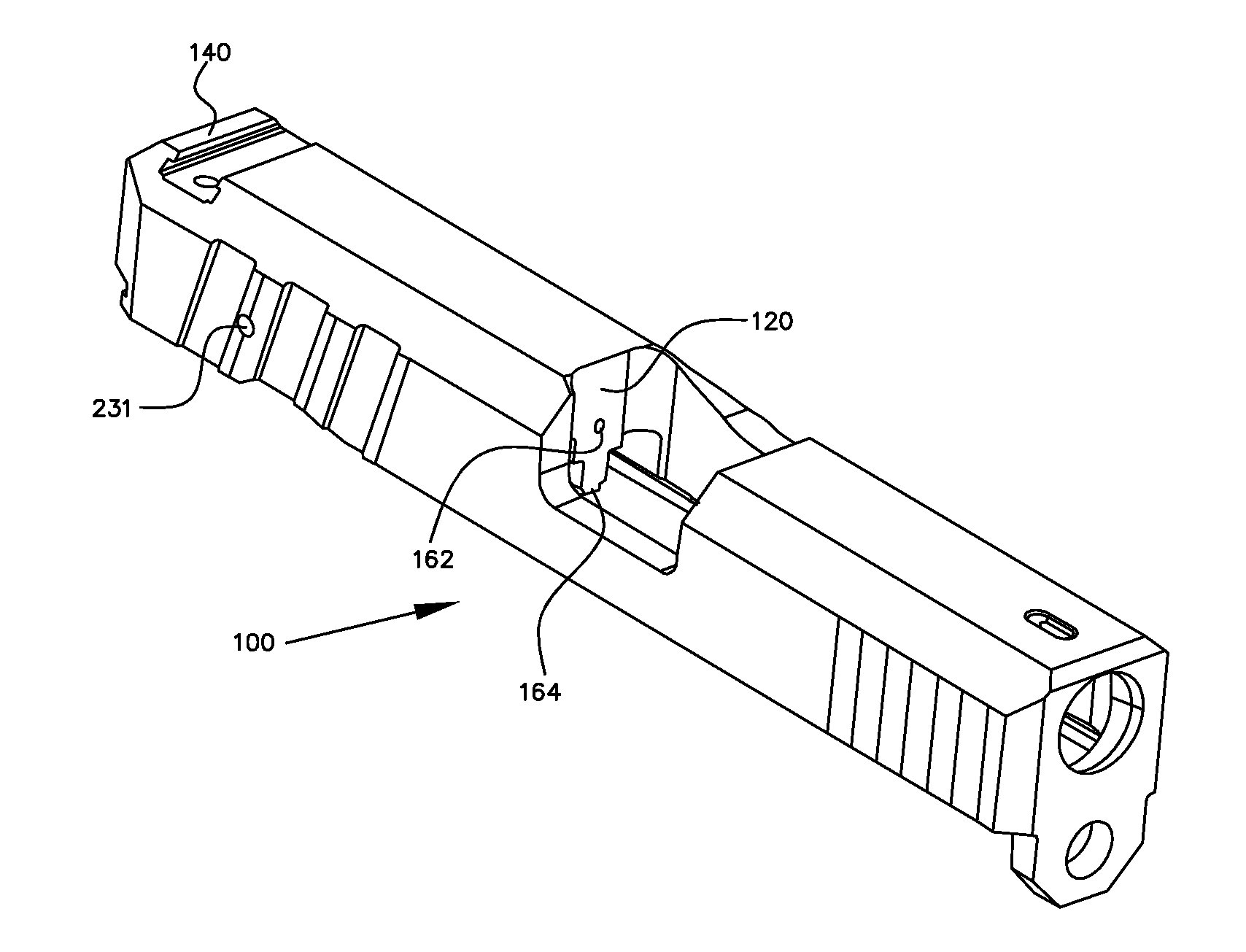
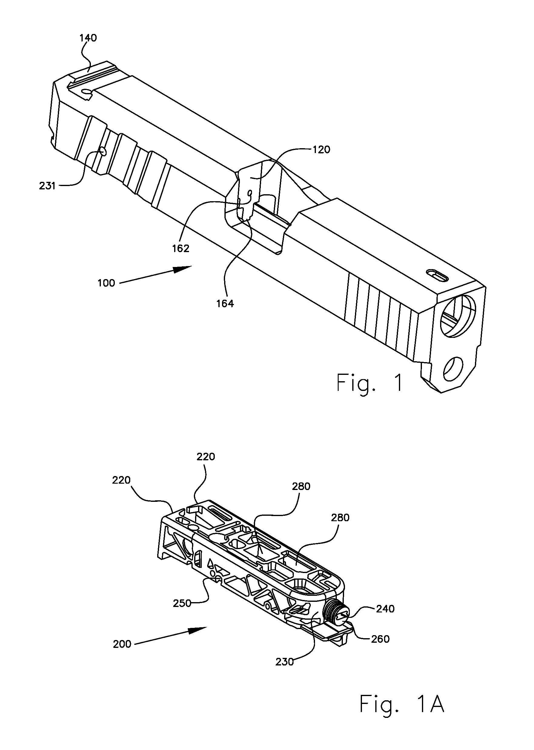
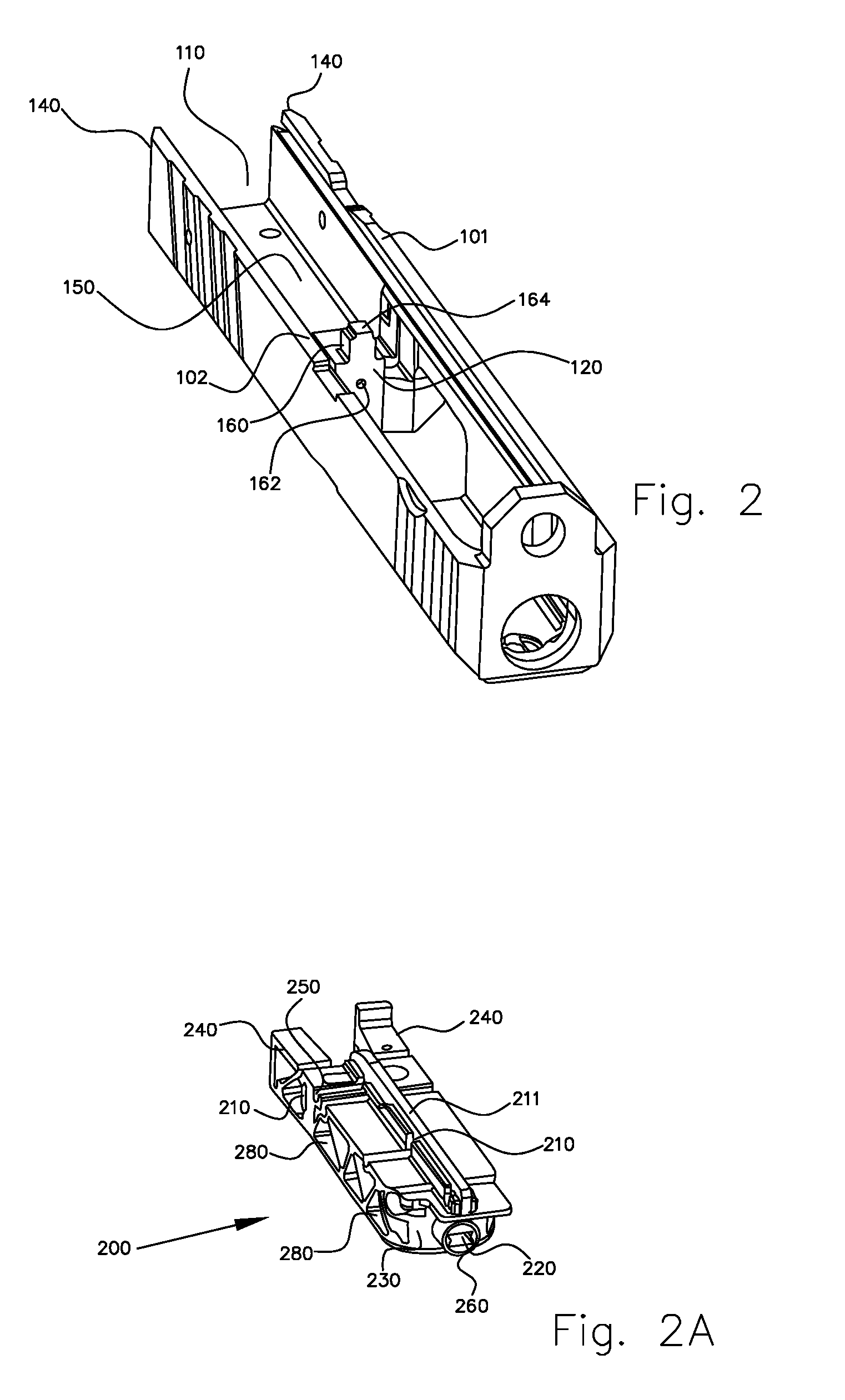
[0025]The breech device 100 of the invention, which is intended for use in a handgun and is shown in FIGS. 1 to 3 in its entirety and in FIGS. 1A to 4 as detailed views, comprises a impact base 120 disposed in a central recess 110 of the breech device 100 and having the form of a front end face of a impact-base member 160 disposed in the central recess. Between the impact base 120 and a rear end face 140 of the breech device, there is disposed a main functional region 150, in which a percussion member 300 for firing a cartridge and a cartridge slide 211 are disposed. The cartridge slide 211 is configured so as to abut cartridges mounted in a magazine in a neutral position of the breech device 100.

[0026]The main functional region 150 is in the form of a main functional element 200 that forms a compact unit and that can be anchored securely and releasably by means of a fixing device in a pre-defined position in an internal profile of the central recess 110 of the breech device 100.

[00...


PUM


Abstract

A breech device (100) for a handgun has an impact base (120) in a central recess (110) in said breech device (100). The impact base (120) is in the form of a front end face of an impact-base member (160) in the central recess. A main functional region (150) is between said impact base (120) and a rear end face (140) of said breech device. At least one percussion member (300) for firing a cartridge and also a surface of a cartridge slide (211) are in the main functional region (150). The surface of the cartridge slide (211) is adapted to abut cartridges mounted in a magazine (100) in a neutral position of the breech device.

Description

CROSS-REFERENCE TO RELATED APPLICATION [0001]Priority is claimed of DE102010047500.9, filed Oct. 5, 2010, the disclosure of which is incorporated by reference herein in its entirety as if set forth at length.BACKGROUND OF THE INVENTION [0002]The invention relates to a breech device for a handgun, which breech device comprises an impact base that is disposed in a central recess of the breech device and that is in the form of a front end face of an impact-base member disposed in the central recess, and a main functional region, which is disposed between the impact base and a rear end face of the breech device and in which at least one percussion member for firing a cartridge and a cartridge slide are disposed, the cartridge slide being adapted to abut cartridges mounted in a magazine in a neutral position of the breech device.[0003]Breech devices of the above type are used in the prior art to carry out an automatic repeating action of a handgun. However, the known breech devices suffe...

Claims


Application Information

Patent Timeline
IPC IPC(8): F41A3/14
CPCF41A3/34
Inventor PFLAUMER, WULF H.WONISCH, FRANZEITH, STEFAN
Owner WALTHER & CO AG
Learn More