Force Balanced Multivoltage Winding Configuration

a multi-voltage winding and configuration technology, applied in the direction of propulsion system, magnetic circuit shape/form/construction, association with control/drive circuit, etc., can solve the problems of large, heavy, inefficient, complex, etc., and achieve the effect of negligible net forces on the rotor

Inactive Publication Date: 2012-08-02
KOLLMORGEN CORP
View PDF15 Cites 3 Cited by
  • Summary
  • Abstract
  • Description
  • Claims
  • Application Information

AI Technical Summary

Benefits of technology

[0011]One object of this invention is to provide a winding configuration for a three phase brushless motor / generator providing different parallel windings that can be wound for different voltages to be run with different loads such that the windings will be force-balanced, creating negligible net forces on a rotor.

Problems solved by technology

This solution is large, heavy, inefficient, and complex.
With single tooth windings, there can be severe force imbalances around the winding on the rotor, which would cause excessive wear on the bearings and noise.

Method used


Image

  • Force Balanced Multivoltage Winding Configuration
  • Force Balanced Multivoltage Winding Configuration
  • Force Balanced Multivoltage Winding Configuration

Examples


Embodiment Construction

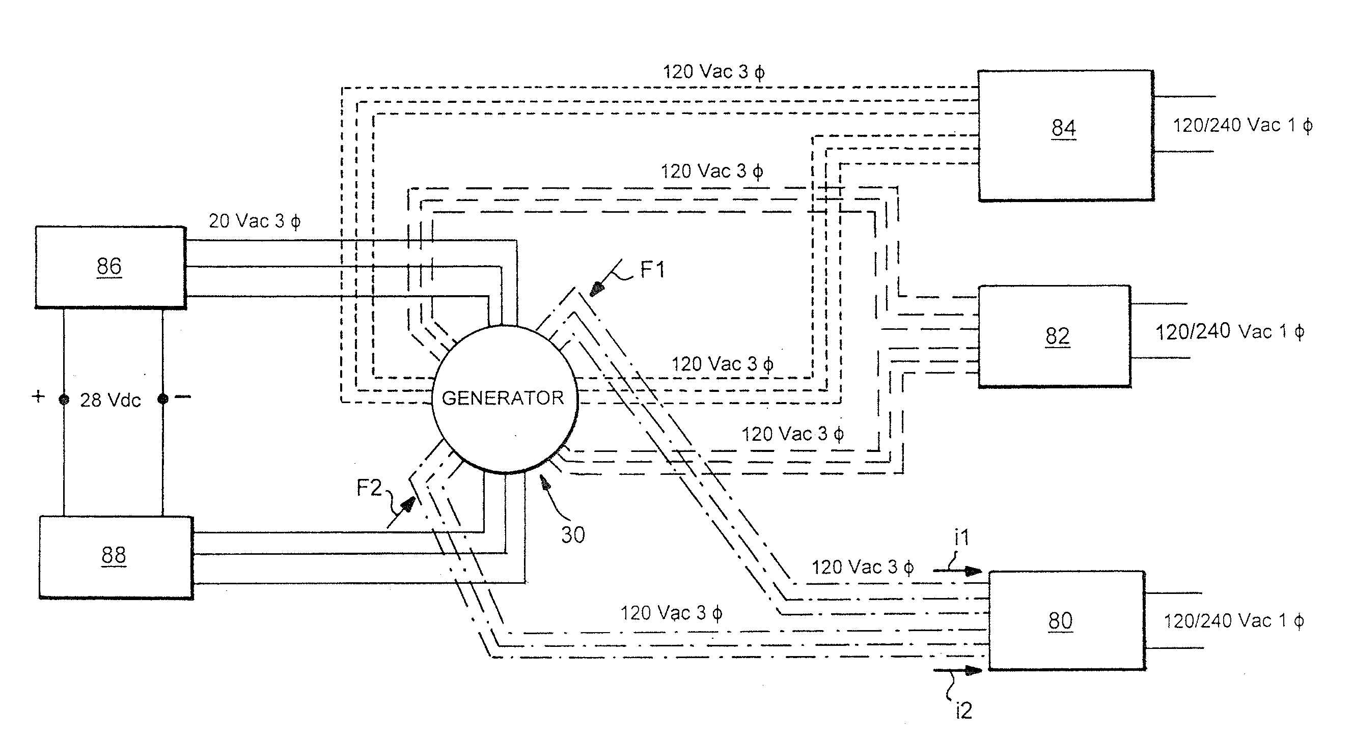
[0021]Although the following description primarily identifies each arrangement illustrated in the drawings and forming the subject matter of the invention as a “generator,” it is to be understood that the principles discussed are equally applicable to electric motor arrangements, and that the invention is not to be limited only to generator applications.

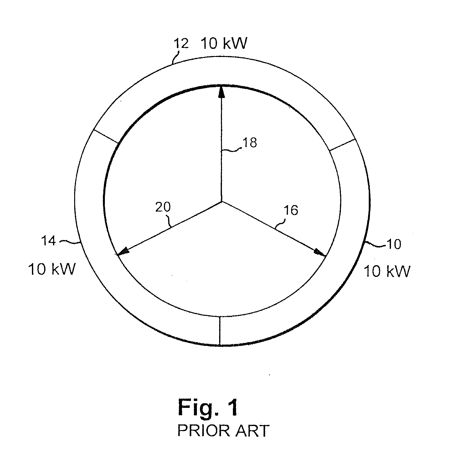
[0022]The known, dual voltage generator schematically illustrated in FIG. 1 has three arc sectors 10, 12, and 14. Power output from each arc sector 10, 12, and 14 may be 10 kW, for example. As is evident from the illustration, when the arc sectors are equally loaded, the resulting force vectors 16, 18, and 20 on the generator rotor (not shown) balance.

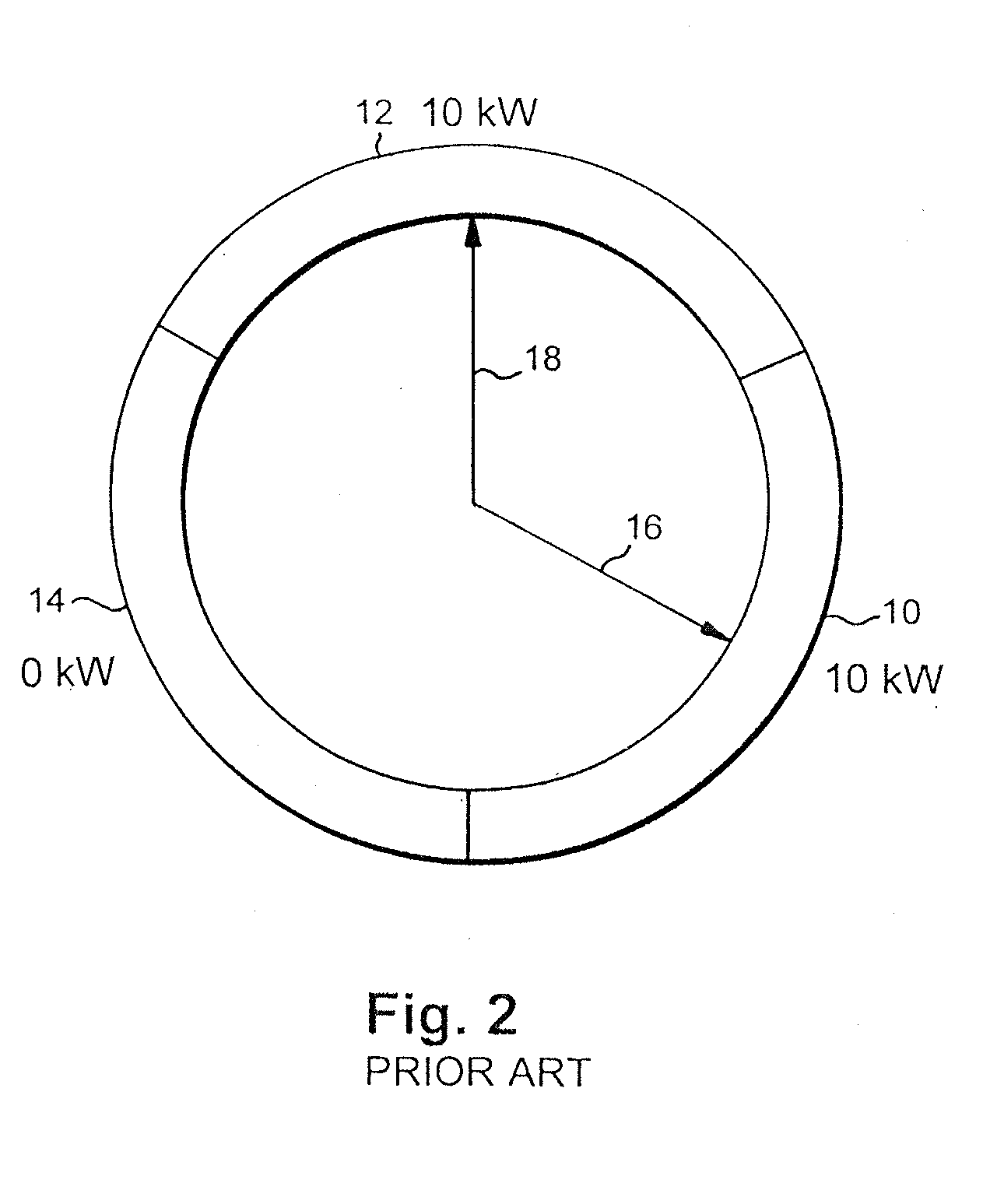
[0023]Issues arise during use of known dual voltage generator designs due to magnetically unbalanced loading caused by unequal electrical loading and adjacent arc construction. FIG. 2, for example, illustrates the generator of FIG. 1 when two adjacent arc sectors 10 and 12 are equally l...


PUM


Abstract

A stator arrangement for a balanced multiple voltage device operable as an electric motor, a generator, or a motor-generator includes a plurality of arc sectors configured so as to surround a rotor of the device. Each of the arc sectors includes a set of stator windings with at least one winding in each set. Those windings in pairs of the arc sectors located at diametrically opposed locations of the stator arrangement are concurrently energized and deenergized in order to eliminate load imbalance on the device.

Description

[0001]This application claims priority under 35 U.S.C. §119(e) to U.S. provisional application Ser. No. 61 / 437,868, filed Jan. 31, 2011, the entire disclosure of which is incorporated by this reference into the present application.BACKGROUND OF THE INVENTION[0002]1. Field of the Invention[0003]This invention concerns an improved stator arrangement for a device operable as an electric motor, a generator, or a motor-generator.[0004]2. Description of Related Art[0005]U.S. Pat. No. 6,242,884 to Lipo et al. discloses a dual stator winding induction machine having a pair of windings with input terminals that are supplied separately with drive power. The two stator windings have a different number of poles to avoid magnetic coupling and to decouple torques produced by the windings.[0006]U.S. Pat. No. 6,710,495 to Lipo et al. discloses a motor having a pair of three-phase windings, with power provided to the windings by two power supplies at the same fundamental frequency and with a compone...

Claims


Application Information

Patent Timeline
Patent Type & Authority Applications(United States)
IPC IPC(8): H02K1/12
CPCH02K19/34H02P25/16H02K2213/06H02K2213/12H02K2213/03H02K11/0073H02K11/046H02K16/04H02K2201/15H02K41/02H02K11/33H02M7/00
Inventor BROWN, GERALD W.FILIP, ETHANTRAGO, BRADLEY A.FUNK, STEPHENBREWSTER, JEFFREY T.
Owner KOLLMORGEN CORP
Why Eureka
Try Eureka