Method of Tracing Touch Paths for a Multi-Touch Panel

Inactive Publication Date: 2012-08-02
TRENDON TOUCH TECHNOLOGY CORPORATION
View PDF13 Cites 21 Cited by
  • Summary
  • Abstract
  • Description
  • Claims
  • Application Information

AI Technical Summary

Benefits of technology

[0007]In view of the foregoing, it is an object of the present invention to provide a method of tracing touch paths instead of scanning all cells of a multi-touch panel, t

Problems solved by technology

However, as touch point density of the touch panel increases, it becomes difficult for processor of the touch panel to finish all the scanning in a limited time period, resulting in loss and time lag in reporting touch points.
A touch panel is susceptible to noise, which causes error or jitter in reporting touch points.
However, conventional noise

Method used


Image

  • Method of Tracing Touch Paths for a Multi-Touch Panel
  • Method of Tracing Touch Paths for a Multi-Touch Panel
  • Method of Tracing Touch Paths for a Multi-Touch Panel

Examples


Embodiment Construction

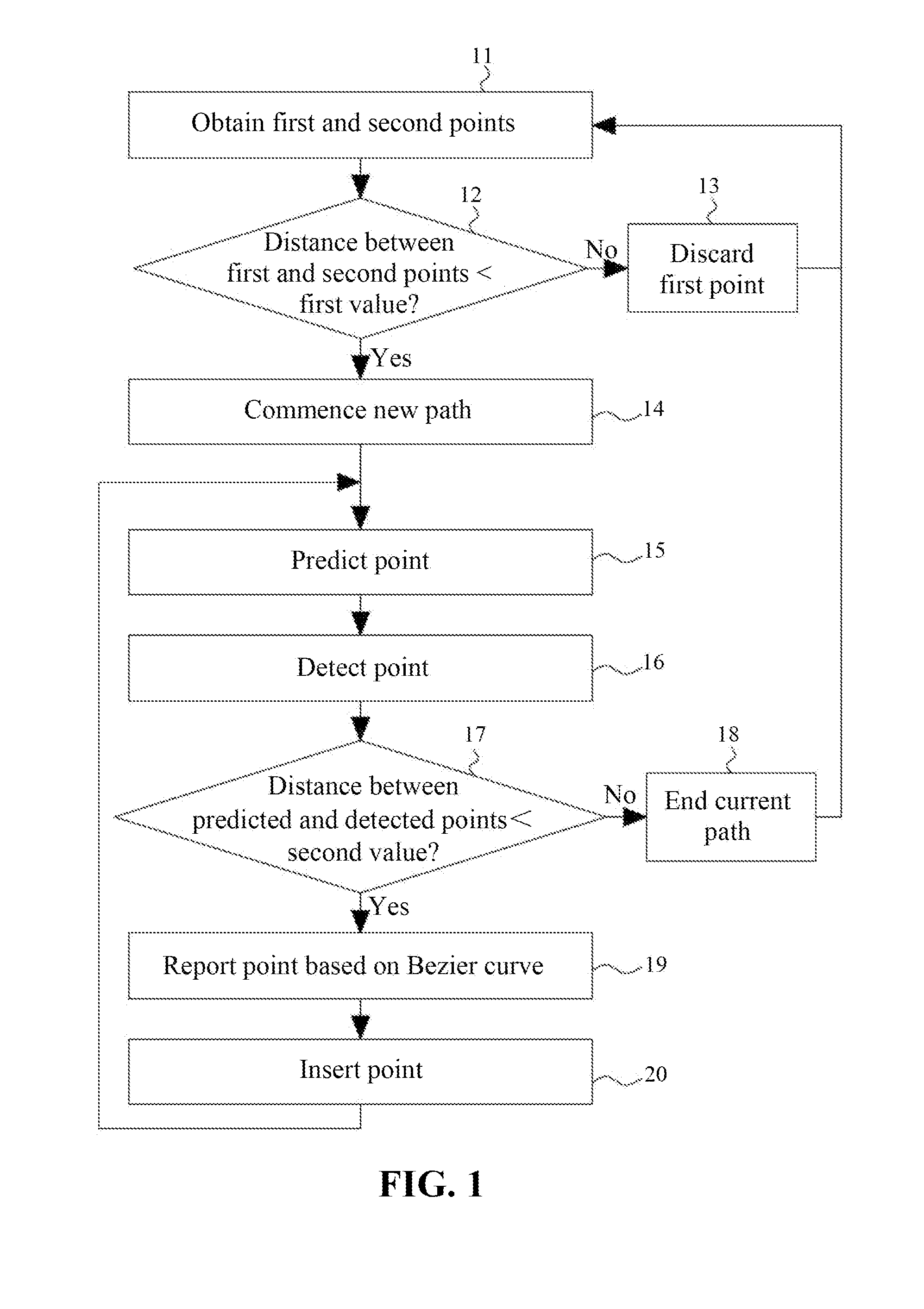
[0011]FIG. 1 shows a flow diagram that illustrates a method of tracing touch paths for a multi-touch panel according to one embodiment of the present invention. The multi-touch panel may be, but not limited to, a capacitive touch panel that measures a change in capacitance introduced, for example, by fingers. The multi-touch panel may be a stand-alone touch panel, or may be integrated with a display panel to constitute a touch screen.

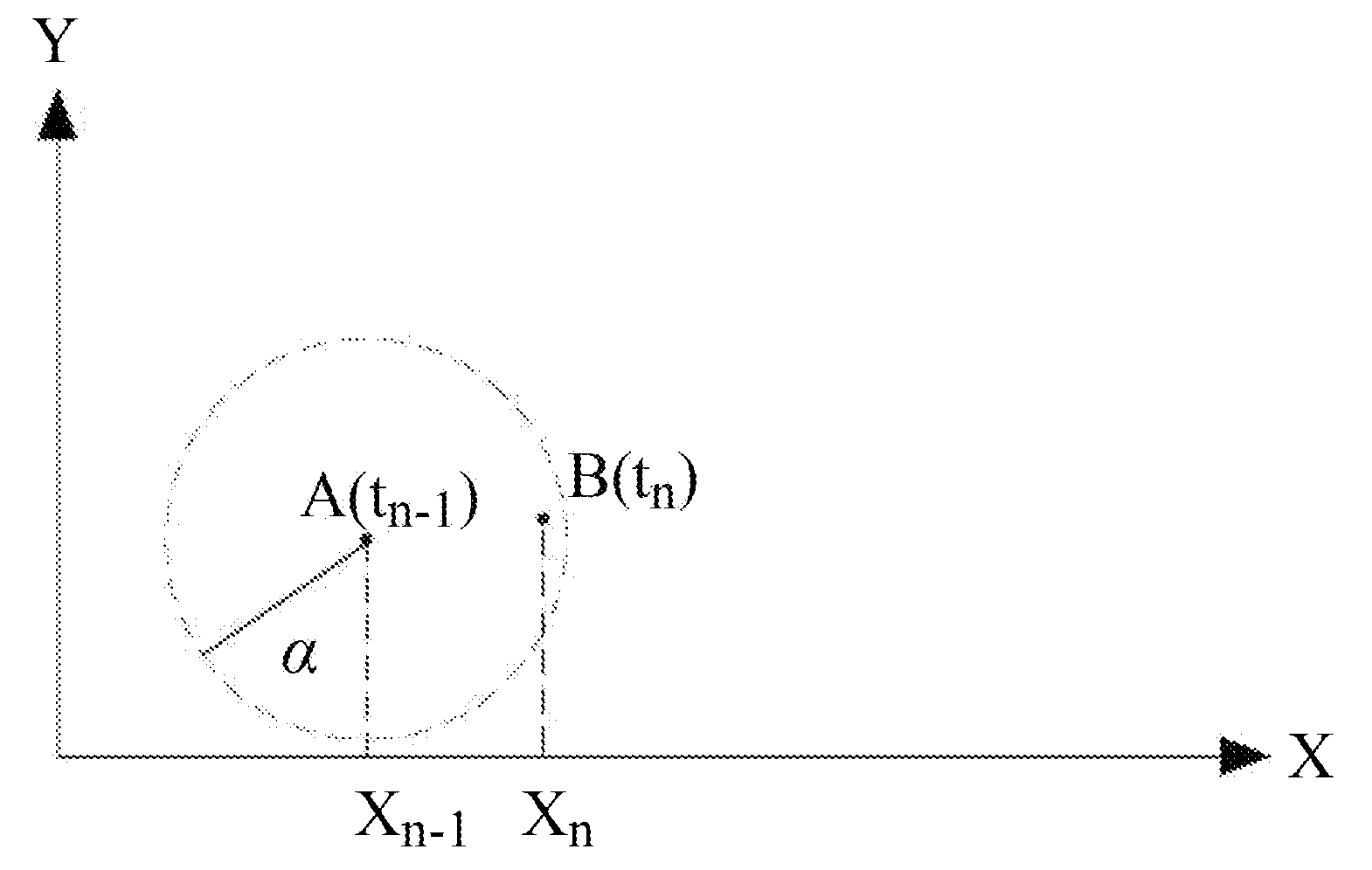
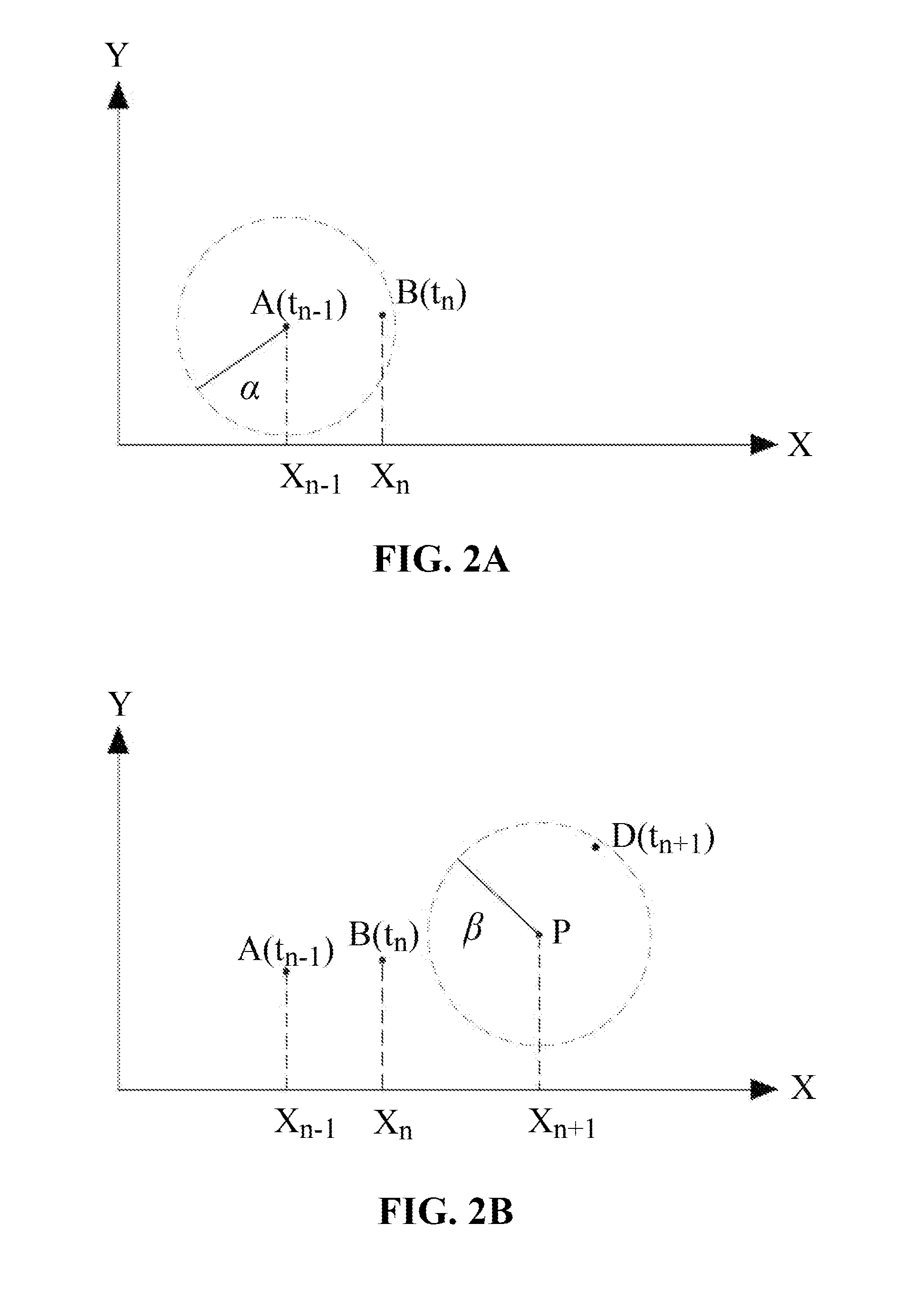
[0012]In step 11, a first touch point and a second touch point are obtained in sequence from a touch panel. The obtained first and second touch points may be stored in a memory device for later use. FIG. 2A shows a touch plane on which an exemplary first touch point A and an exemplary second touch point B are obtained at time tn−1 and tn respectively. For succinctness of the figure, only coordinates along X axis are shown.

[0013]Subsequently, in step 12, a first distance between the first touch point and the second touch point is determined and a check i...


PUM


Abstract

A method of tracing touch paths for a multi-touch panel is disclosed. A basis touch point obtained from the multi-touch panel, a predicted touch point generated according to the basis touch point, and a detected touch point obtained from the multi-touch panel are provided. A reported touch point is then generated according to the basis touch point, the predicted touch point and the detected touch point based on a parametric curve.

Description

BACKGROUND OF THE INVENTION[0001]This Application claims the benefit of People's Republic of China Application No. 201110038743.4, filed Jan. 31, 2011.TECHNICAL FIELD[0002]The present invention generally relates to a touch panel, and more particularly to a method of tracing touch paths for a multi-touch panel.DESCRIPTION OF THE RELATED ART[0003]A touch panel detects presence and location of a touch point typically by scanning each cell of the touch panel. However, as touch point density of the touch panel increases, it becomes difficult for processor of the touch panel to finish all the scanning in a limited time period, resulting in loss and time lag in reporting touch points.[0004]A touch panel is susceptible to noise, which causes error or jitter in reporting touch points. Accordingly, a variety of noise-resisting filtering mechanisms performed either in spatial domain or time domain are used to suppress the noise. However, conventional noise-resisting mechanisms disadvantageousl...

Claims


Application Information

Patent Timeline
IPC IPC(8): G06F3/041G06F3/0488
CPCG06F2203/04808G06F3/04883G06F3/0416
Inventor CHANG, CHING-YANGWU, HSIANG-CHENG
Owner TRENDON TOUCH TECHNOLOGY CORPORATION
Why Eureka
Try Eureka