Method For Spatial Smoothing In A Shader Pipeline For A Multi-Projector Display

a multi-projector display and shader pipeline technology, applied in the field of multi-projector systems, can solve the problems of reducing the visual color intensities of the output projector, and incorrectly simplifying the conditions that exist with the actual projector, so as to achieve more visually acceptable color perception, improve the visual color intensities, and improve the effect of output projector control

Active Publication Date: 2012-08-02
SEIKO EPSON CORP
View PDF1 Cites 11 Cited by
  • Summary
  • Abstract
  • Description
  • Claims
  • Application Information

AI Technical Summary

Benefits of technology

[0013]GPU shaders are used for several key operations in the multi-projector display system. The present invention is directed to a shader method and apparatus that provides better control over an output projector by the GPU using a color result from the multitude of other multi-projector shader processing steps. The process achieves a more visually acceptable color perception on a multi-projector display screen. The effect provides expanded visual color intensities that can better smooth coarse steps in a typical color range.

Problems solved by technology

Unfortunately the combination from two projectors in this overlap region is additive and results in a brighter region with color differences.
However, this assumption incorrectly simplifies conditions that exist with actual projectors.
Device light output levels are seldom identical and so the 50% / 50% approach cannot ensure success.
Again, in actual practice, this better but still simple technique results in some visual bands or gaps in the image.
But, there was no method available to determine the best formula for a particular situation, i.e., a particular set of projectors.
The multi-projector display system places high demands on this color range in the output projectors.
Digital processes of all kinds stretch, compress, reshape, or otherwise manipulate source content and continually challenge color accuracy.
However, even with so many color output choices, blending regions can experience trouble with producing smooth, visually continuous gradients of changing luminance.
Projectors with very low black points are often more difficult to adjust as the range of color choices at such low luminance is small.

Method used


Image

  • Method For Spatial Smoothing In A Shader Pipeline For A Multi-Projector Display
  • Method For Spatial Smoothing In A Shader Pipeline For A Multi-Projector Display
  • Method For Spatial Smoothing In A Shader Pipeline For A Multi-Projector Display

Examples


Embodiment Construction

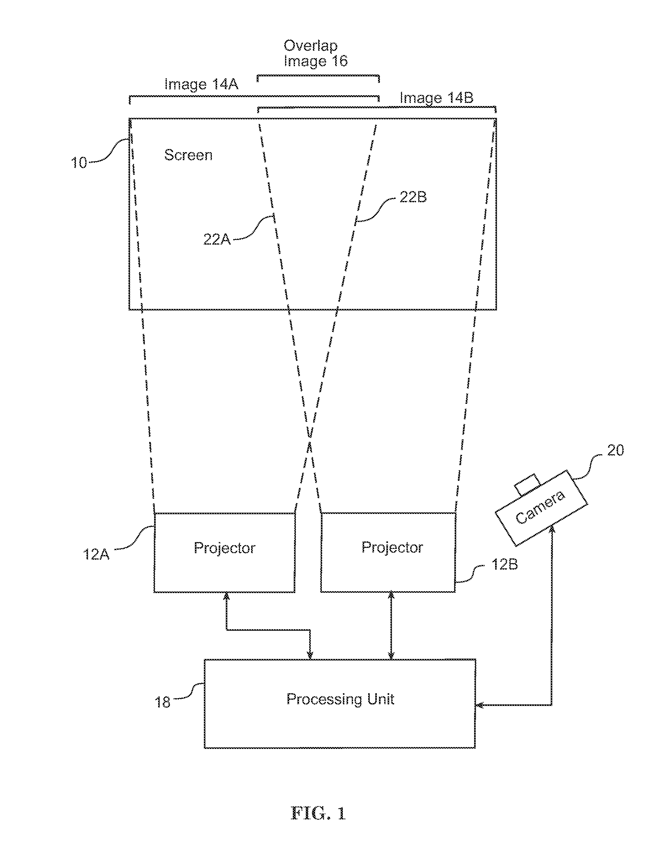
[0031]FIG. 1 shows a general system block diagram of the environment of the present invention. In this system, multiple projectors are controlled and coordinated to provide a large display region such as a wall display. In FIG. 1, just two projectors are illustrated for simplicity; however, in a large system three, four, or more projectors may be utilized. Eight projectors are used in an exemplary 2×4 configuration. As shown, projectors 12A and 12B each project an image onto a portion of the screen 10, with image 14A occupying one portion, image 14B occupying a second portion, and overlap image 16 occupying a portion that represents the intersection of images 14A and 14B projected onto screen 10. Using multiple projectors in this manner with overlapping and complementary projections can be used to provide a very large, but still very bright and clear, continuous display.

[0032]Various approaches are available to build the multi-projector display of FIG. 1. It is well known that in or...


PUM


Abstract

A device, computer-readable medium or method for adjusting pixels of a source image prior to being output to a display device comprising: segmenting the pixels of the source image into spatial groups; assigning an adjustment method to each pixel in a group; creating an adjustment matrix set with rows (or columns) corresponding to the plurality of adjustment methods, and columns (or rows) corresponding to a range of pixel values that exceed a discrete output device value, and adjustment values as entries; receiving a pixel of the source image in a graphics processing unit (GPU) and using the GPU to: determine the pixel's relative location in its spatial group and its corresponding adjustment method; determine the range of pixel values that the value of the pixel exceeds a discrete output device value: select an adjustment value from the adjustment matrix set; and adjust the value of the pixel by the adjustment value.

Description

CROSS-REFERENCE TO RELATED APPLICATION(S)[0001]This application is related to commonly owned U.S. patent application Ser. No. 12 / 501,162, filed Jul. 10, 2009, and U.S. patent application Ser. No. 12 / 730,470 filed Mar. 24, 2010, which are hereby incorporated by reference in their entirety.BACKGROUND[0002]The present invention is related to a multiple projector system. In this system multiple projectors are controlled and coordinated to provide a large display region such as a wall display. In such a display the goal is to provide a seamless image. However, in certain areas there is an overlap region where two projectors contribute light output to the same portion of the display surface. Unfortunately the combination from two projectors in this overlap region is additive and results in a brighter region with color differences. The overlap region is thus a visible band in the overall displayed image.[0003]In order to minimize the visual band that occurs from the overlap region, a numbe...

Claims


Application Information

Patent Timeline
Patent Type & Authority Applications(United States)
IPC IPC(8): G09G5/00
CPCG06F3/1446G09G3/001H04N9/3194H04N9/3147H04N9/3182G09G2300/026
Inventor IVASHIN, VICTOR
Owner SEIKO EPSON CORP
Why Eureka
Try Eureka