Goniophotometr for measuring 3D light intensity distribution of light source

a goniophotometer and light source technology, applied in the direction of photometry using electric radiation detectors, optical radiation measurement, instruments, etc., can solve the problems of mechanical scanning apparatus often occupying a rather large volume, mechanism is typically large and cumbersome, and cannot be quickly placed. , to achieve the effect of simple and compact goniophotometer, low cost and simple construction

Inactive Publication Date: 2012-08-02
B&M OPTICS
View PDF6 Cites 20 Cited by
  • Summary
  • Abstract
  • Description
  • Claims
  • Application Information

AI Technical Summary

Benefits of technology

[0008]It is another object of the invention to provide a compact goniophotometer that is of low cost and simple construction. And this simple and compact goniophotometer advantageously facilitates rapid measurement rate.
[0009]In one embodiment, the present invention is directed to a goniophotometer comprising an arc reflector, a holder, a detector, a driving device and a computing unit. The holder is provided for positioning a light source at the arc center of the arc reflective surface of the reflector. The detector is substantially disposed at the arc center of the arc reflector and aimed at the arc reflective surface of the reflector. The driving device is provided for rotating the holder with respect to the reflector as well as the detector about an axis running through the light source in such a way that the detector can capture light reflected by the reflector in all directions from the light source. The computing unit is configured to convert a detection result of the detector into a measurement value for describing the light intensity distribution of the light source.

Problems solved by technology

However, such mechanical scanning apparatus often occupy a rather large volume due to the necessity of scanning at specified radii and also produces merely a two dimensional distribution of the luminous intensity of the light source.
However, this mechanism is typically large and cumbersome and does not allow for rapid positioning.
Thus, a lengthy time for measurement would be required.

Method used


Image

  • Goniophotometr for measuring 3D light intensity distribution of light source
  • Goniophotometr for measuring 3D light intensity distribution of light source
  • Goniophotometr for measuring 3D light intensity distribution of light source

Examples


Embodiment Construction

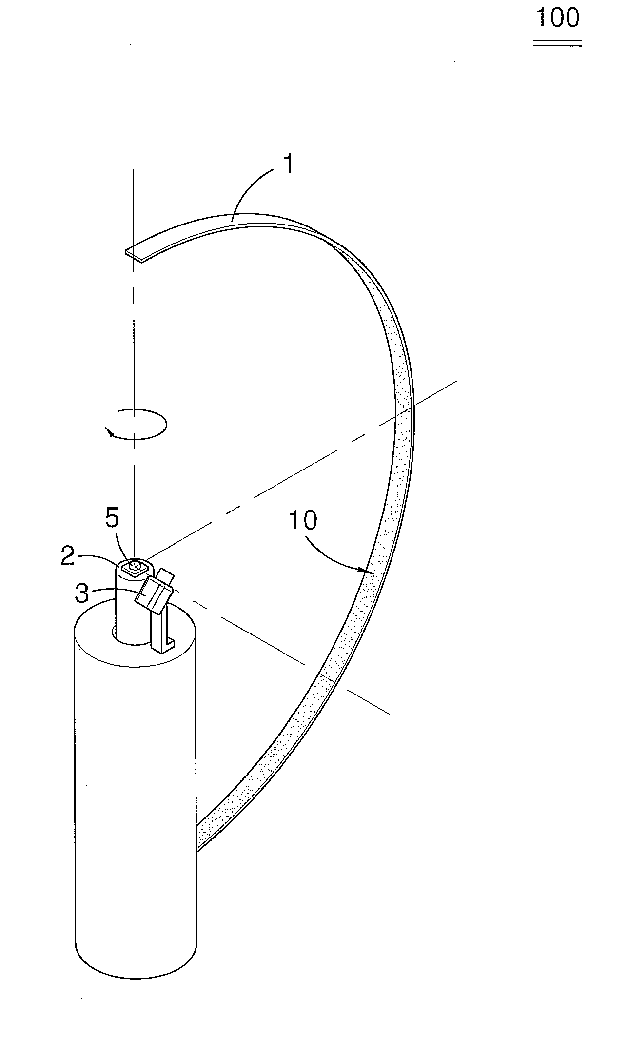
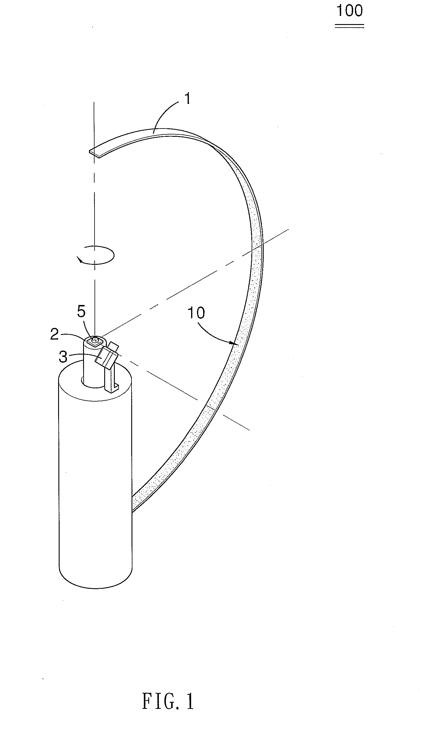
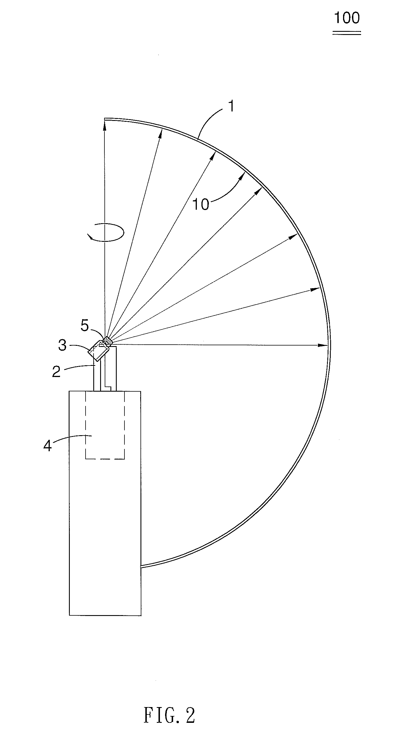
[0017]Referring now to FIGS. 1 and 2, there is illustrated a goniophotometer 100 for measuring or characterizing the radiation pattern of a light source in accordance with a first embodiment of the present invention. The goniophotometer 100 includes an arc reflector 1, a holder 2, a detector 3, a driving device 4 (FIG. 2) and a computing unit (not shown). It is noted that the goniophotometer 100 is, but not limited to, a luminous intensity distribution meter.

[0018]As shown in FIG. 1, the reflector 1 has an arc reflective surface 10 that is arc-shaped in cross section. The arc reflective surface 10 of the reflector 1 is coated with a diffuse reflectance material, such as barium sulfate, for light reflection. The holder 5 is provided for positioning a light source, such as a LED, at the arc center of the arc reflective surface 10 of the reflector 1, as depicted in FIG. 1. In other words, every point on the arc reflective surface 10 of the reflector 1 is exactly the same distance from ...


PUM


Abstract

A goniophotometer includes an arc reflector; a holder for positioning a light source at the center of the arc reflector; a stationary detector substantially disposed at the center of the arc reflector and aimed at an arc reflective surface of the reflector; a driving device for rotating the holder with respect to the reflector and the detector about an axis of the light source; and a computing unit configured to convert a detection result of the detector into a measurement value.

Description

BACKGROUND OF INVENTION[0001]1. Field of Invention[0002]This invention relates to a goniophotometer for measuring the three dimensional distribution of the luminous intensity of an optical source such as light emitting diode (LED), optical fiber, huninaire or the like.[0003]2. Related Prior Art[0004]Techniques are known in the art for measuring or characterizing the radiation pattern of a light source by utilizing a goniometer in combination of an optical detector. One such goniophotometeric measurement, as disclosed in Taiwan Patent No. I236530, is typically made by rotating the detector on a radial arm of the goniometer about the light source to be measured. The detector scans through angles and measures light output as a function of angle. However, such mechanical scanning apparatus often occupy a rather large volume due to the necessity of scanning at specified radii and also produces merely a two dimensional distribution of the luminous intensity of the light source.[0005]In ac...

Claims


Application Information

Patent Timeline
IPC IPC(8): G01N21/47
CPCG01J1/0242G01J1/0411G01J2001/4247
Inventor KUO, HUNG-PIN
Owner B&M OPTICS
Why Eureka
Try Eureka