Thermal compensation element with wave spring

a wave spring and thermal compensation technology, applied in the direction of bearing unit rigid support, mechanical apparatus, rotary machine parts, etc., can solve the problems of loss of preload, increase preload, increase frictional torque, etc., and achieve increased preload, increased frictional torque, and different thermal expansion coefficients

Inactive Publication Date: 2012-08-02
SCHAEFFLER TECH AG & CO KG
View PDF11 Cites 3 Cited by
  • Summary
  • Abstract
  • Description
  • Claims
  • Application Information

AI Technical Summary

Benefits of technology

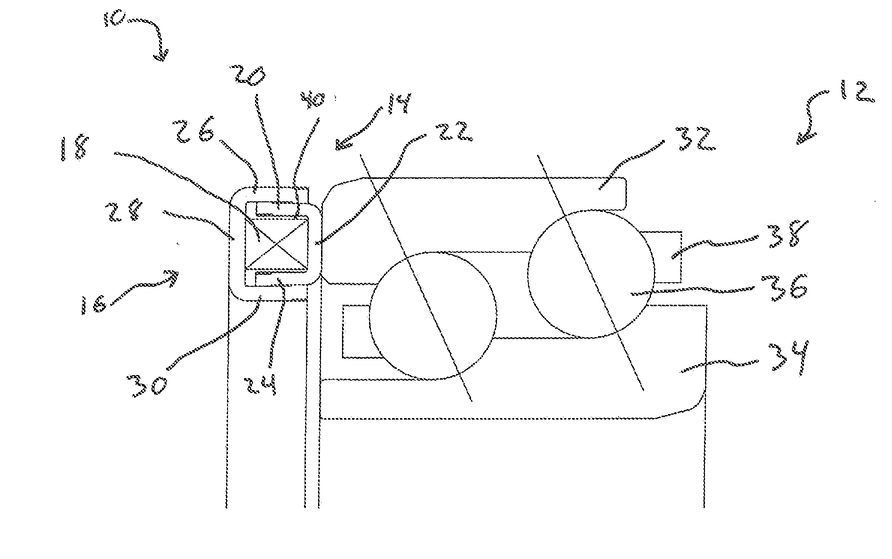
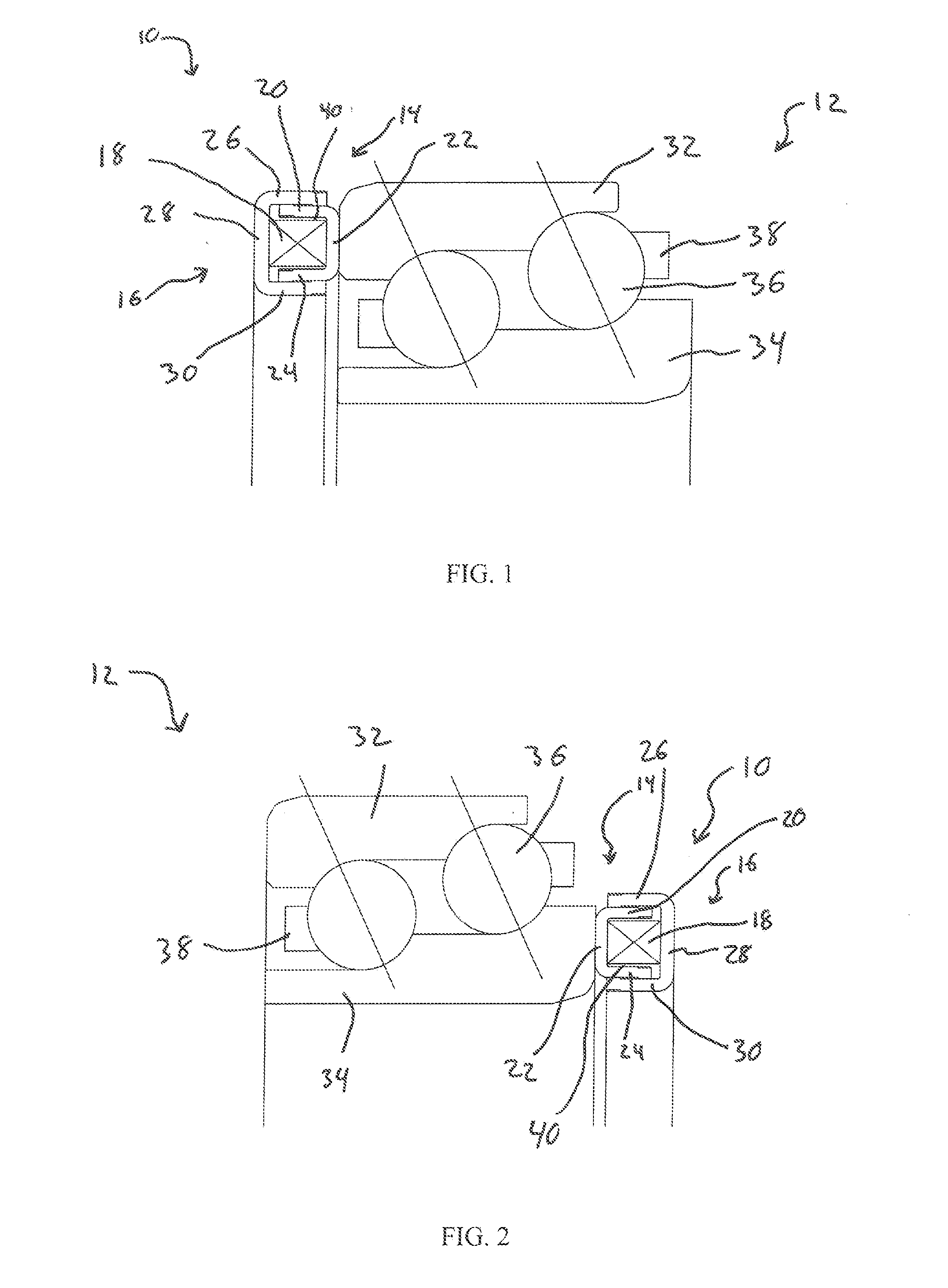
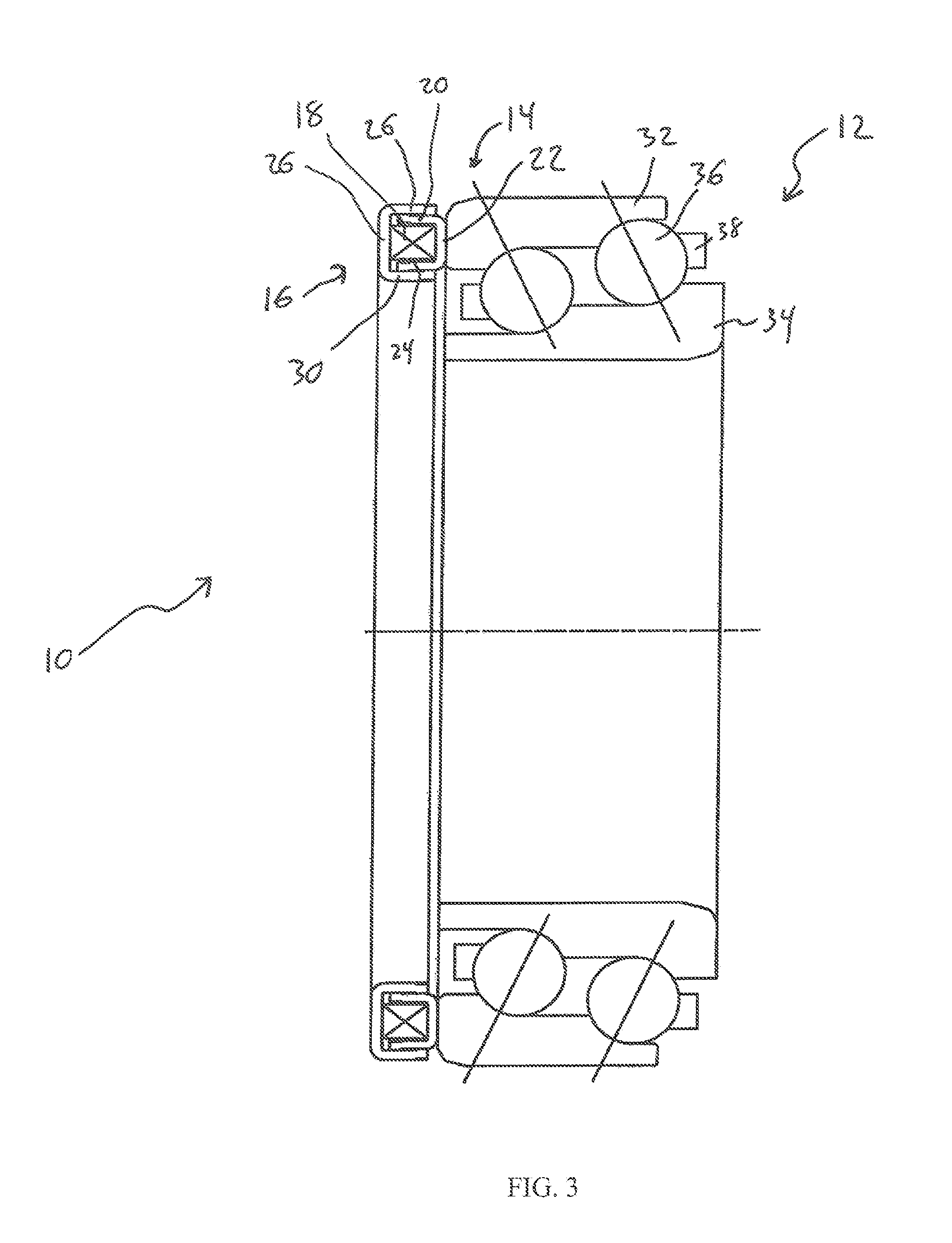
[0004]The present invention is directed to a thermal compensation element, which is positioned between a bearing and a shoulder of a housing or a shaft and can account for high loads and extreme variations of temperature that may occur to a bearing and shaft system when the shaft and an associated housing for a transmission, gearbox, axle or the like are comprised of different materials and have different coefficients of thermal expansion (e.g., sheet metal shaft and an aluminum housing). Due to the differences of materials and different coefficients of thermal expansion, the rates of expansion and contraction can vary causing a wide variation in bearing preload over a range of temperatures. This variation can lead to an increased preload, an increased frictional torque, and / or a loss of preload, which in turn can lead to a reduction in the life of the bearing and noise.

Problems solved by technology

This variation can lead to an increased preload, an increased frictional torque, and / or a loss of preload, which in turn can lead to a reduction in the life of the bearing and noise.

Method used


Image

  • Thermal compensation element with wave spring
  • Thermal compensation element with wave spring
  • Thermal compensation element with wave spring

Examples


first embodiment

[0038]FIG. 7 shows the thermal compensation element 100. As shown, a first wall 102 of the inner ring 104, which has a U-Shaped cross-section, has a first protrusion 106 and a second wall 108 of the inner ring 104 has a second protrusion 110. The first protrusion 106 is in sliding contact with an inner face of a first wall 112 of an outer ring 114 and the second protrusion 110 is in sliding contact with an inner face of a second wall 116 of the outer ring 114. Also, the first wall 112 of the outer ring 114, which has U-Shaped cross-section, is bent inward and is in sliding contact with an outer face of the first wall 102 of the inner ring 104 and the second wall 116 of the outer ring 114 is bent inward and is in sliding contact with an outer face of the second wall 110 of the inner ring 104. The configuration allows for axial movement of the inner ring 104 and the outer ring 114 to maintain a proper preload while ensuring the inner ring 104 and the outer ring 114 do not axially sepa...

second embodiment

[0039]FIG. 8 shows the thermal compensation element 200. As shown, a first wall 202 of an inner ring 204, which has U-Shaped cross-section, is bent outward and is in sliding contact with an inner face of a first wall 206 of an outer ring 208 and a second wall 210 of the inner ring 204 is bent outward and is in sliding contact with an inner face of a second wall 212 of the outer ring 208. Similarly, the first wall 206 of the outer ring 208, which also has a U-Shaped cross-section, is bent inward and is in sliding contact with an outer face of the first wall 202 of the inner ring 204 and the second wall 212 of the outer ring 208 is bent inward and is in sliding contact with an outer face of the second wall 219 of the inner ring 204. The configuration allows for axial movement of the inner ring 204 and the outer ring 208 to maintain a proper preload while ensuring the inner ring 204 and the outer ring 208 do not axially separate.

third embodiment

[0040]FIG. 9 shows the thermal compensation element 300. As shown, a groove 302 extends along an outer face of a first wall 304 of an inner ring 306, which has a U-Shaped cross-section, up to a first tab 308 which protrudes outward, toward a first wall 310 of an outer ring 312 and a groove 314 extends along an outer face of a second wall 316 of the inner ring 306, up to a second tab 318 which protrudes outward, toward a second wall 320 of the outer ring 312. Similarly, a groove 322 extends along an inner face of the first wall 310 of the outer ring 312, which also has a U-Shaped cross-section, up to a third tab 324 which protrudes inward, toward the first wall 304 of the inner ring 306 and a groove 326 extends along an inner face of the second wall 320 of the outer ring 312, up to a fourth tab 328 which protrudes inward, toward the second wall 316 of the inner ring 306. The first tab 308 and the second tab 318 are each in sliding contact with the grooves 322, 326, respectively, of o...


PUM


Abstract

A thermal compensation element which has an inner ring, an outer ring, and a washer. The washer is arranged within the inner ring and the outer ring is mounted over the inner ring, encapsulating the washer, which can be a split wave spring. The inner ring and the outer ring each have retention features to ensure they are retained relative to each other. The thermal compensation, which is positioned between a housing or a shaft, can account for variations in loading and/or temperature that may occur to a bearing and a shaft system when the shaft and an associated component are made of different materials and have different coefficients of thermal expansion by ensuring a proper axial preload is maintained on the bearing.

Description

[0001]This application claims the priority U.S. 61 / 437,189 filed Jan. 28, 2011 which is incorporated by reference herein.FIELD OF INVENTION[0002]The present invention relates generally to bearings and more particularly to a thermal compensation element which accounts for thermal changes that may occur in applications utilizing bearings or the like that require axial preload for proper functionality.BACKGROUND OF THE INVENTION[0003]The use of an elastomeric material to compensate for thermal expansion and contraction of components which have dissimilar materials and are used in conjunction with each other are known, see, for example, U.S. Pat. No. 5,028,152. Such an arrangement includes inserting an elastomer into a cavity within a machined outer ring of a bearing, bonding an elastomer to a metallic backing, or encapsulating an elastomer within two cups which are snapped into a cavity in an outer ring or an inner ring. However, there are various drawbacks to such arrangements. For ex...

Claims


Application Information

Patent Timeline
Patent Type & Authority Applications(United States)
IPC IPC(8): F16C25/08F16C33/30
CPCF16C2300/54F16C35/073F16C35/077F16C25/083F16C19/525F16C19/56F16C19/182F16F1/328F16C2361/61
Inventor INCE, MARION JACKZHONG, GUIHUISOUTHAM, ROBERTSCHWAB, CHARLESTURNER, MICHAELLEE, BRIAN
Owner SCHAEFFLER TECH AG & CO KG
Why Eureka
Try Eureka