Stackable structural reactors

a technology of stackable structure and reactor, which is applied in the direction of liquid-gas reaction of thin-film type, gas-gas reaction process, separation process, etc., can solve the problems of unfavorable heat transfer, unsatisfactory clogging of gas flow in reactor tubes, and limited ceramic pellets

Active Publication Date: 2012-08-02
JOHNSON MATTHEY PLC
View PDF4 Cites 49 Cited by
  • Summary
  • Abstract
  • Description
  • Claims
  • Application Information

AI Technical Summary

Benefits of technology

[0005]A reactor for carrying out catalytic reactions is provided. The reactor comprises a fan arranged on a central rod in a reactor tube. The fan can have radial fluid ducts for directing fluid flow through the reactor. The fluid ducts are effective for radially guiding fluid flow towards the reactor tube to assist in heat transfer. The fan has a top surface, bottom surface and an outer diameter face. The radial fluid ducts, formed by corrugations in the fan, terminate along the outer diameter face of the fan to form fluid duct openings, for example triangular openings, that face the reactor tube wall and thus promoting heat transfer from the reactor tube into the interior of the reactor.

Problems solved by technology

The ceramic pellets break and become damaged over time and can form a powder in the reactor tubes, which can undesirably clog gas flow in the reactor tubes and negatively affect heat transfer.
Moreover, the ceramic pellets are limited in the amount of heat that can be transferred throughout the reactor tube core.
Low heat transfer from the heat source located outside the reactor tubes necessitates high furnace temperatures, increased energy costs, and reactor tube walls that can lead to shortened or impaired reactor tube life.
Mal-distribution of ceramic pellets in the core can create zones with poor reaction characteristics and hot spots on the tube, leading to poor performance and / or life.

Method used


Image

  • Stackable structural reactors
  • Stackable structural reactors
  • Stackable structural reactors

Examples


Embodiment Construction

[0030]As used herein, when a range such as 5-25 is given, this means at least or more than 5 and, separately and independently less than, and not more than 25. Materials of construction for all reactor components or parts thereof as discussed herein can include any suitable material as known in the art, for example, metal, non-ferrous metal, metal foil, steel, stainless steel, alloys, foils, non-metals such as plastics or glass, ceramic, or combinations thereof.

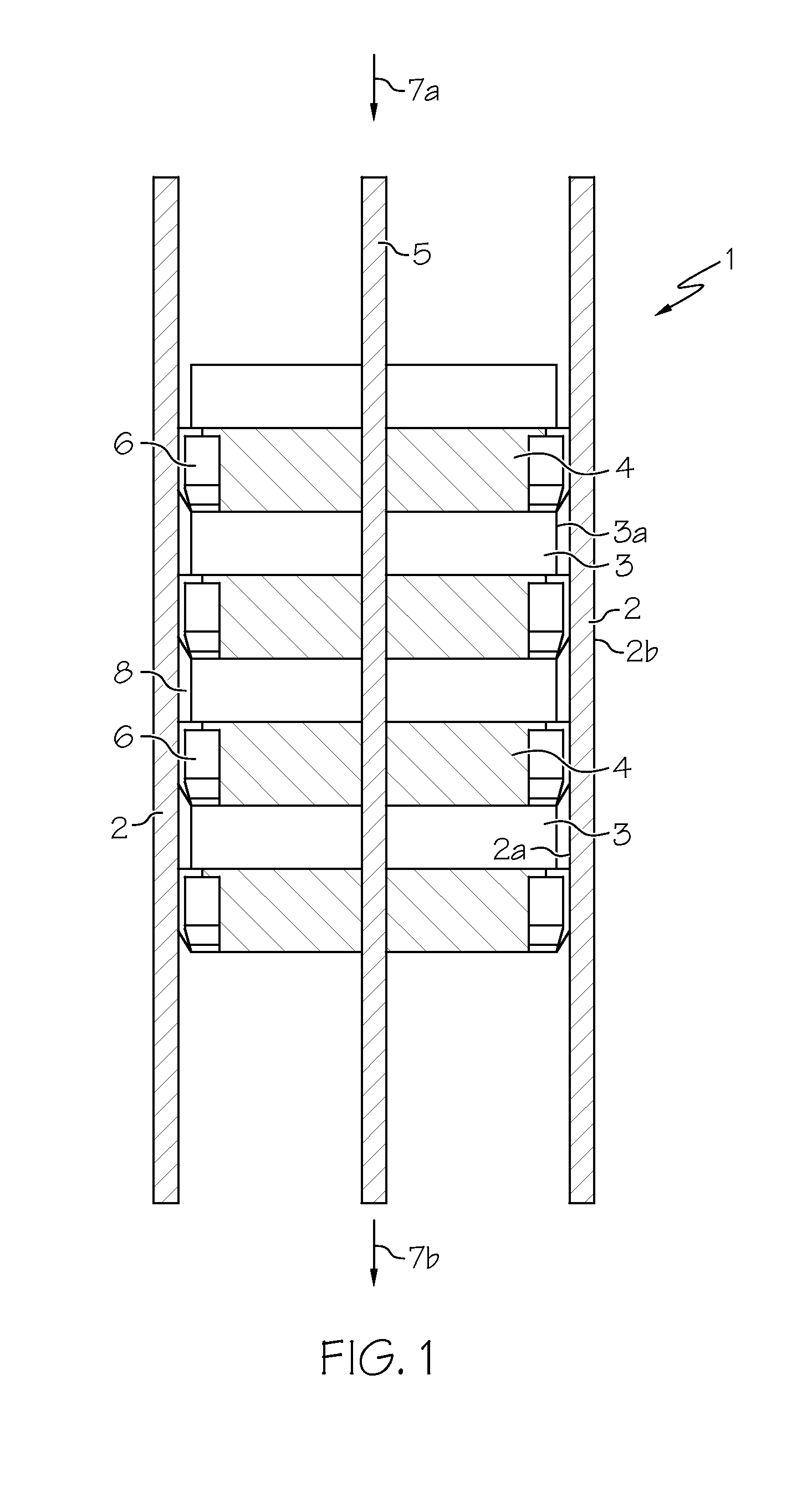
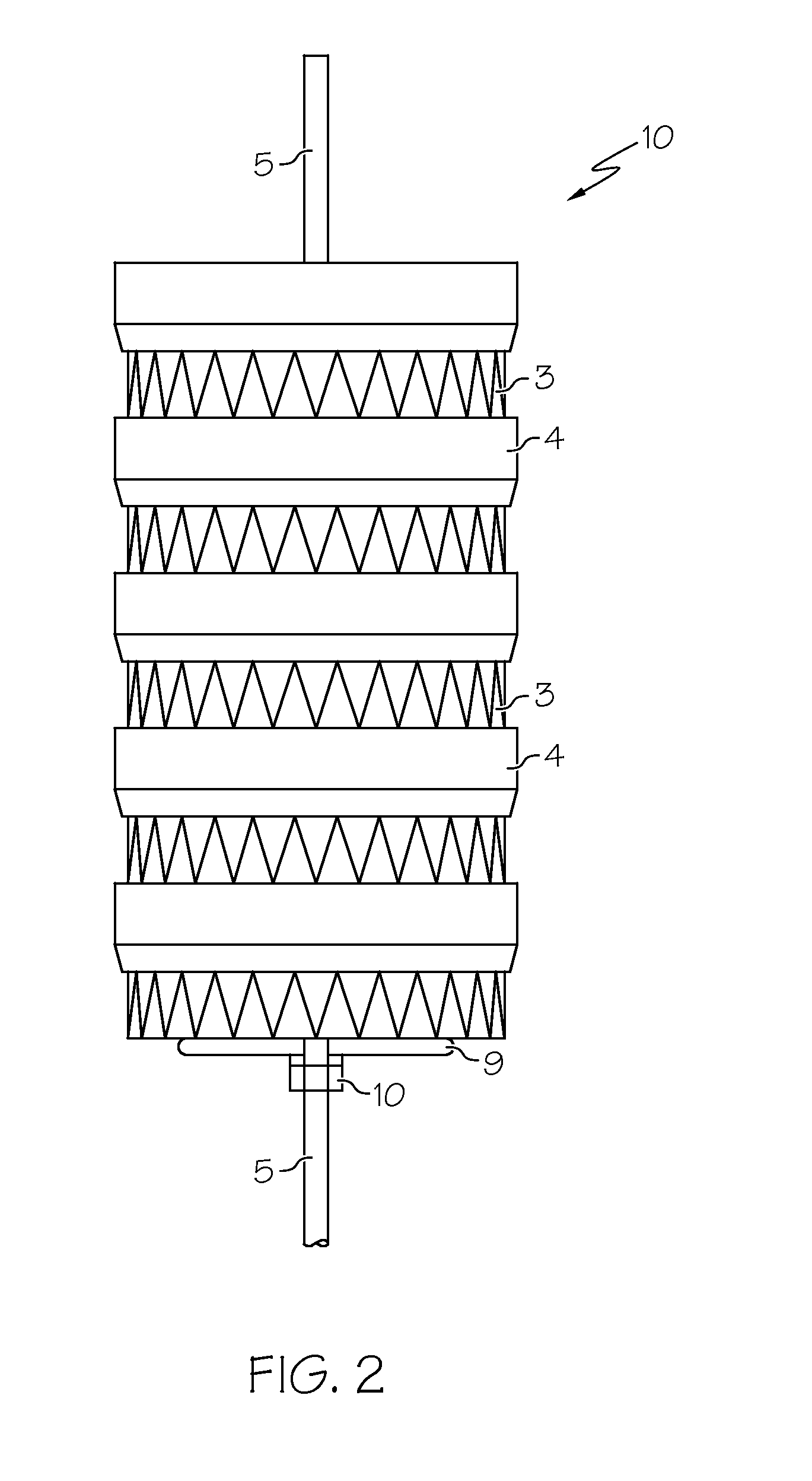
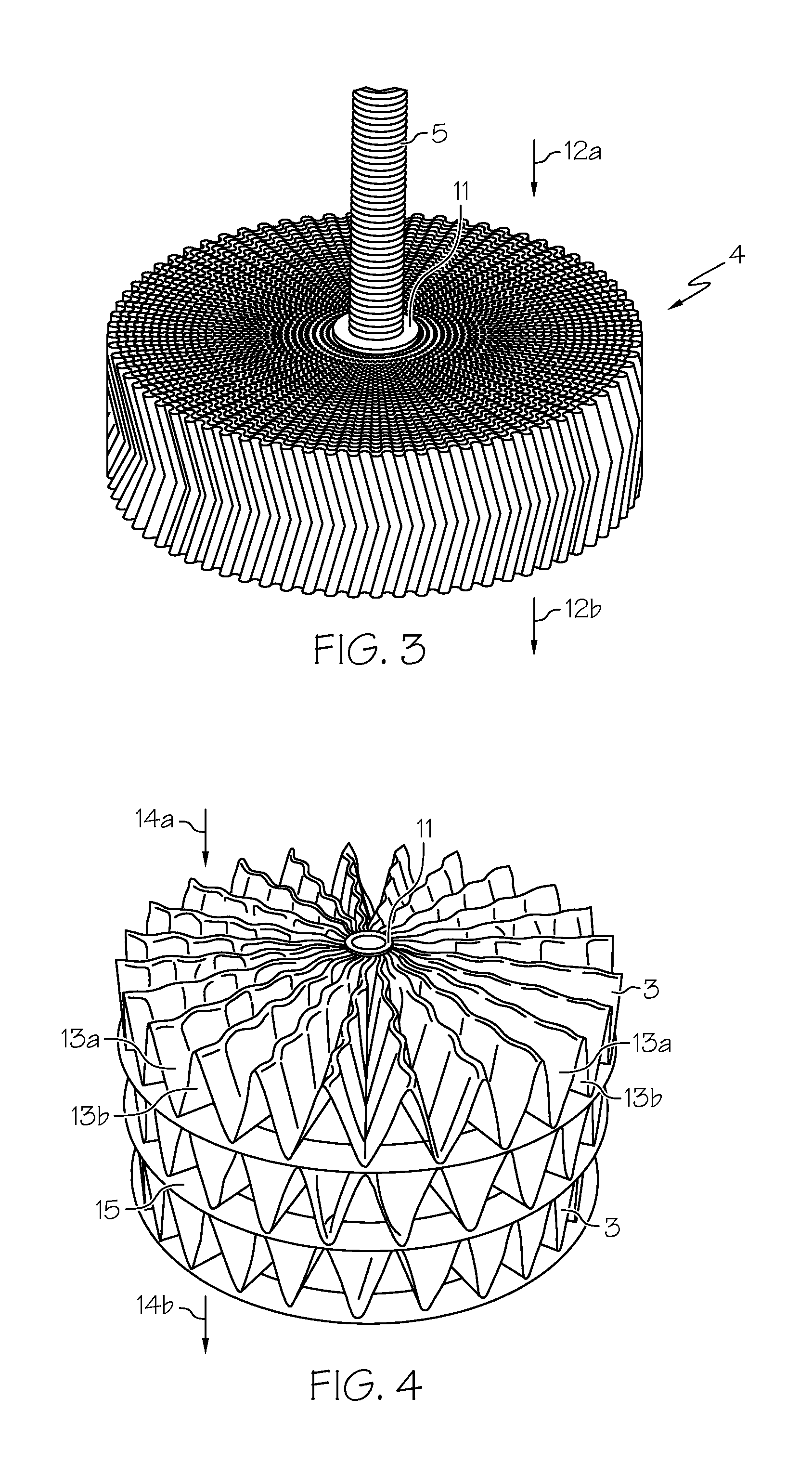
[0031]The reactors as described herein, sometimes referred to as a stackable structural reactors (“SSR”), can include multiple components arranged around a center support, such as a central rod or mandrel, pipe, post or the like in order to form a monolith of general annular cross section as viewed in the direction of flow of fluid through the reactor. As described herein, various modifications and embodiments of the reactors and associated reactor components can be used.

[0032]An example structure of a reactor 1 is shown in F...


PUM

PropertyMeasurementUnit
outer diameteraaaaaaaaaa
incline angleaaaaaaaaaa
inner diameteraaaaaaaaaa

Abstract

A reactor for carrying out catalytic reactions. The reactor includes a reactor component optionally arranged on a central rod in a reactor tube. The reactor component can have fluid ducts for directing fluid flow through the reactor. The fluid ducts are effective for increasing heat transfer in the reactor. The reactor component can further have a washer attached to a top or bottom surface for directing fluid flow.

Description

[0001]This application claims the benefit of U.S. Provisional Application No. 61 / 437,103, filed Jan. 28, 2011, which is incorporated herein by reference in its entirety.FIELD[0002]The present inventions relate to improved stackable structural reactors having increased efficiency and productivity, and in particular, improved stackable structural reactors having component arrangements for increased heat transfer and reaction efficiency.BACKGROUND[0003]Reformers, such as those used to produce hydrogen, generally contain reactor tubes exposed to a heat source, for example a furnace, to support endothermic reactions. Other types of reactions, such an exothermic, can require exposure to a cooling source, such as a cooling jacket. Reactor tubes can be loaded with ceramic pellets impregnated with catalyst or having a catalyst coating for carrying out a reaction. The ceramic pellets break and become damaged over time and can form a powder in the reactor tubes, which can undesirably clog gas ...

Claims


Application Information

Patent Timeline
Patent Type & Authority Applications(United States)
IPC IPC(8): B01J19/00B01F23/30
CPCB01J19/249B01J8/0242B01J2219/1944B01J2219/2453B01J2219/2459B01J2219/2479B01J2219/2485B01J2219/2493B01J2219/2496B01J2219/3221B01J2219/32231B01J2219/32408B01J2219/32466C01B3/382C01B2203/0227C01B2203/1035C01B2203/143B01J19/32B01D53/86B01J8/06B01J19/18B01F23/30Y02E60/32B01J2219/2461
Inventor WHITTENBERGER, WILLIAM A.BRUNSON, GORDON W.DAVIS, BRIAN L.ROMESBERG, TODD A.BARTOS, RANDALL J.WHITTENBERGER, JOSEPH W.
Owner JOHNSON MATTHEY PLC
Why Eureka
Try Eureka