Monitoring the health of a blowout preventer

a technology of monitoring the health of a blowout preventer and a control device, which is applied in the direction of sealing/packing, instruments, and wellbore/well accessories, etc., can solve the problems of failure of the well, increased sudden pressure in the wellbore itself, and complex control systems of the conventional blowout preventer

Inactive Publication Date: 2012-08-02
BP CORP NORTH AMERICA INC
View PDF2 Cites 130 Cited by
  • Summary
  • Abstract
  • Description
  • Claims
  • Application Information

AI Technical Summary

Benefits of technology

[0008]A computerized monitoring system and corresponding method of monitoring the status and health of a blowout preventer. The system includes a graphics display, for example as deployed at the drilling site and viewable by on-site personnel, at which a graphical user interface (GUI) displays the health of various sealing elements and control systems by way of “traffic light” indicators. The health indicators are evaluated, by the monitoring system, based on a risk profile for each of the ind

Problems solved by technology

As known in the art, the penetration of high-pressure reservoirs and formations during the drilling of an oil and gas well can cause a sudden pressure increase (“kick”) in the wellbore itself.
A significantly large pressure kick can result in a “blowout” of drill pipe, casing, drilling mud, and hydrocarbons from the wellbore, which can result in failure of the well.
In modern deep-drilling wells, particularly in offshore production, the control systems involved with conventional blowout preventers have become quite complex.
Such tests may also be required by regulatory agencies, considering the danger to human and environmental safety presented by well blowouts.
Of course, such periodic tests consume personnel and equipment resources, and can require shutdown of the drilling operation.
However, in conventional blowout preventer control systems, these various inputs and measurements generate a large amount of data over ti

Method used


Image

  • Monitoring the health of a blowout preventer
  • Monitoring the health of a blowout preventer
  • Monitoring the health of a blowout preventer

Examples


Embodiment Construction

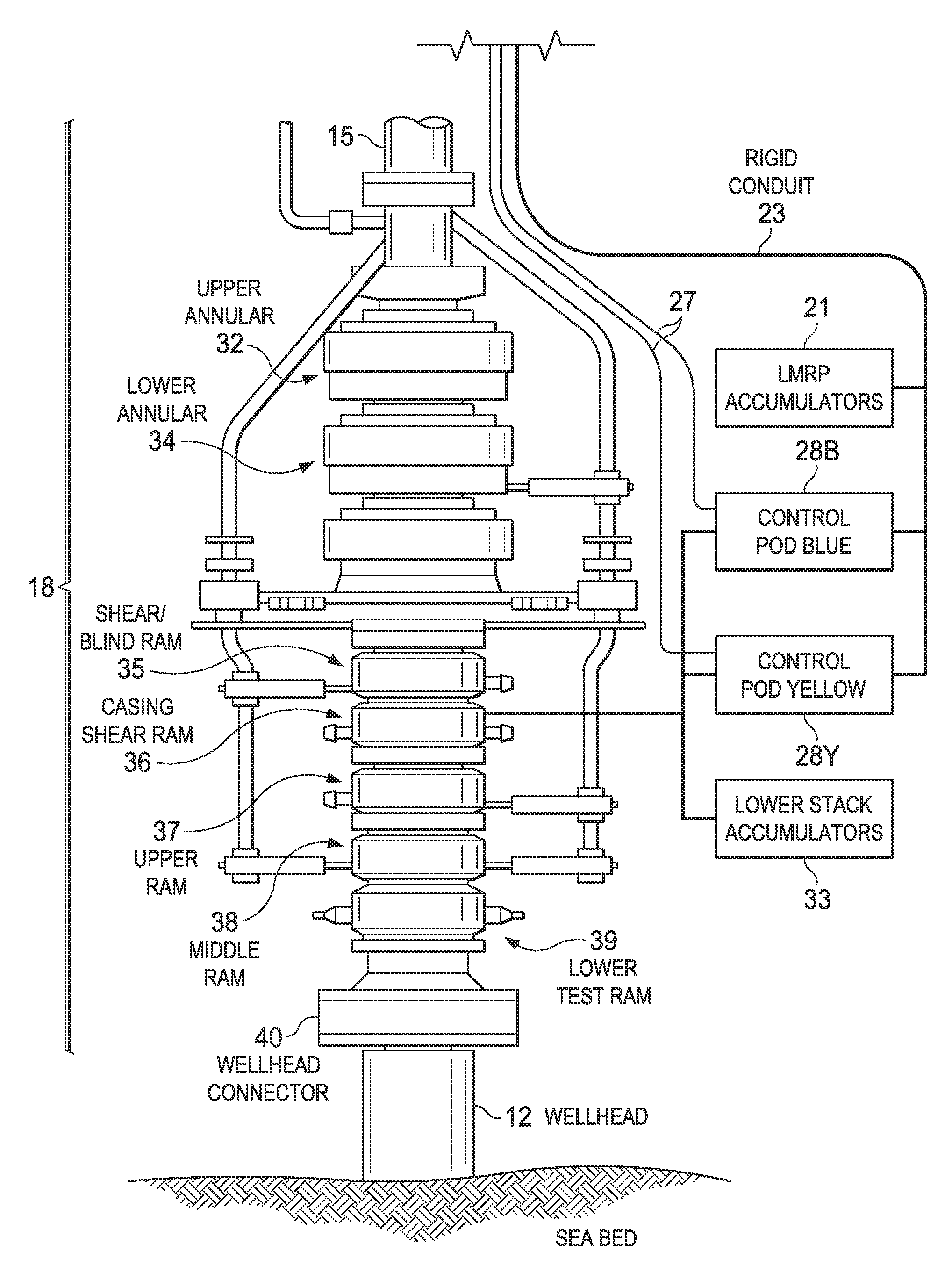
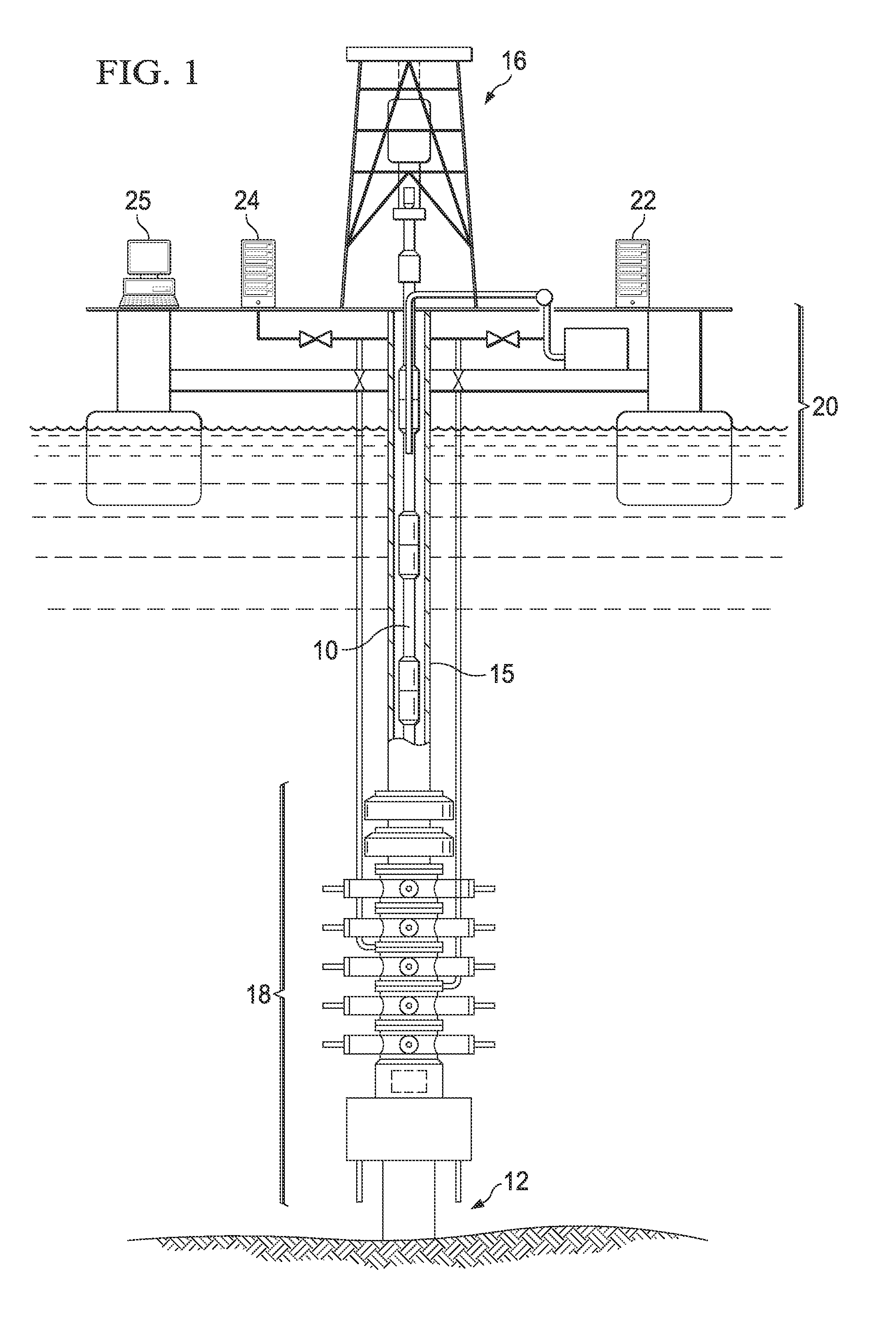
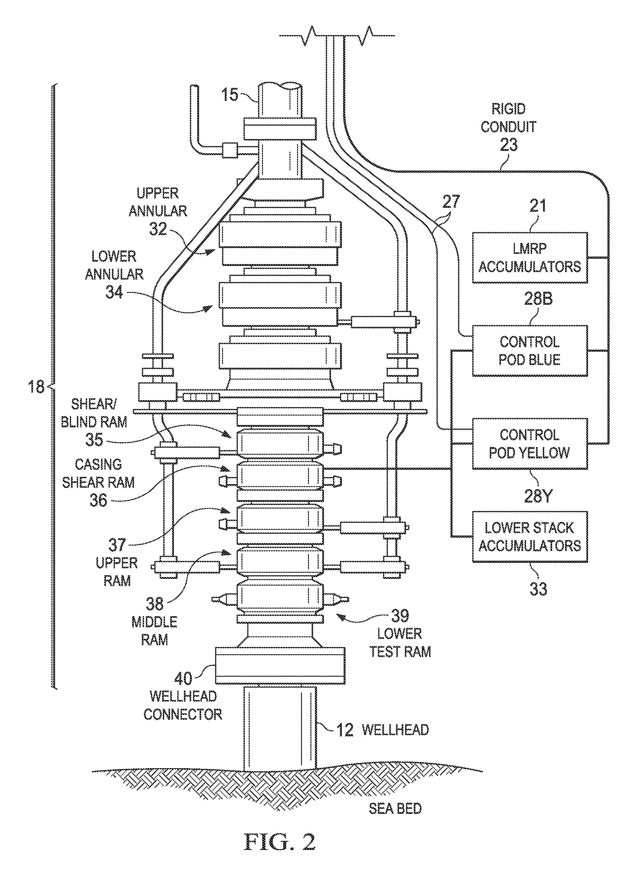
[0018]For simplicity and illustrative purposes, the principles of the present teachings are described by referring mainly to exemplary embodiments thereof, namely as implemented into a computerized monitoring system for determining the health and status of a blowout preventer in an offshore drilling context. However, it is of course contemplated that this disclosure can be readily applied to and provide benefit in to other drilling and production applications beyond that described in this disclosure, including blowout preventers deployed at the surface. One of ordinary skill in the art would readily recognize that the same principles are equally applicable to, and can be implemented in, all types of information and systems, and that any such variations do not depart from the true spirit and scope of the present teachings. Moreover, in the following detailed description, references are made to the accompanying figures, which illustrate specific exemplary embodiments. Electrical, mech...


PUM


Abstract

A computerized monitoring system and corresponding method of monitoring the status and health of a blowout preventer. The system includes a graphics display at which a graphical user interface (GUI) displays the health of various sealing elements and control systems by way of “traffic light” indicators. The health indicators are evaluated, by the monitoring system, based on a risk profile for each of the indicated elements and control systems. The risk profiles are evaluated based on inputs such as measurement inputs, feedback signals, mechanical positions, diagnostic results, drilling conditions, and other status information of the blowout preventer at a given time and based on levels of redundancy and levels of deviation from normal conditions. The GUI includes recent history of changes in operating condition, and alarm indications such as poor health, along with the times of those events.

Description

CROSS-REFERENCE TO RELATED APPLICATIONS[0001]This application claims priority to U.S. Provisional Application No. 61 / 436,731 filed Jan. 27, 2011, the disclosure of which is incorporated herein in its entirety.FIELD[0002]This disclosure relates generally to hydrocarbon production. Embodiments of this disclosure are more specifically directed to the operation of well control devices such as blowout preventers.DESCRIPTION OF THE RELATED ART[0003]As known in the art, the penetration of high-pressure reservoirs and formations during the drilling of an oil and gas well can cause a sudden pressure increase (“kick”) in the wellbore itself. A significantly large pressure kick can result in a “blowout” of drill pipe, casing, drilling mud, and hydrocarbons from the wellbore, which can result in failure of the well.[0004]Blowout preventers (“BOPs”) are commonly used in the drilling and completion of oil and gas wells to protect drilling and operational personnel, and the well site and its equip...

Claims


Application Information

Patent Timeline
IPC IPC(8): G06F19/00E21B34/04
CPCE21B41/0007E21B33/064
Inventor MCKAY, JAMES EDWINSTARLING, GAVIN TRISCOTT
Owner BP CORP NORTH AMERICA INC
Why Eureka
Try Eureka