Methods and reconfigurable systems to optimize the performance of a condition based health maintenance system

a health maintenance system and architecture technology, applied in the direction of digital computers, testing/monitoring control systems, instruments, etc., can solve the problems of cumbersome performance or significant modification costs, user to live with cumbersome performance or pay significant modification costs, and the complexity of a cbm system remains high

Inactive Publication Date: 2012-08-02
HONEYWELL INT INC
View PDF4 Cites 26 Cited by
  • Summary
  • Abstract
  • Description
  • Claims
  • Application Information

AI Technical Summary

Benefits of technology

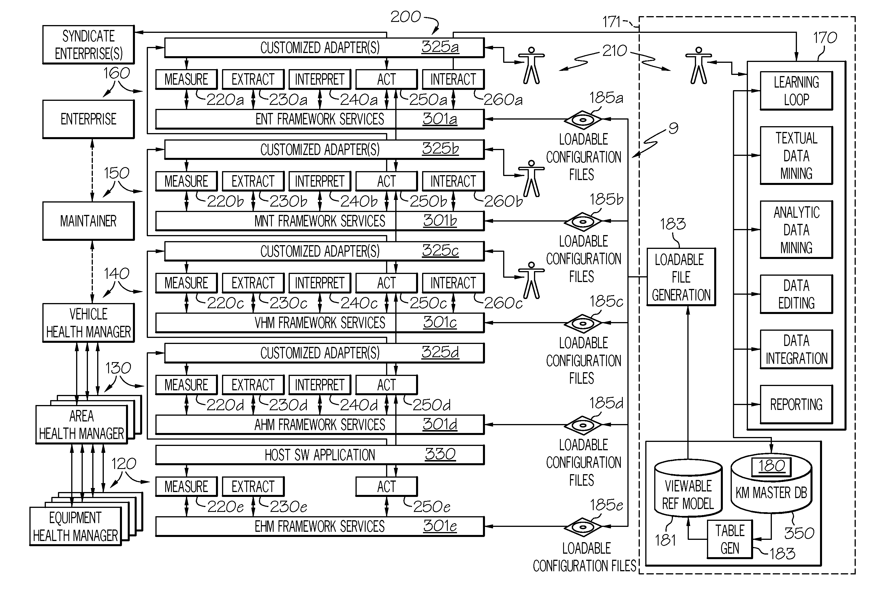
[0112]Thus, the configuration files provide the information that allows the standardized executable application modules to operate and to interact with each other. Specifically this interaction is controlled via the workflow service which obtains all of its directives from the configuration files 185 to enable or disable functionality of the standardized executable application modules as well as provide processing of data within the node (120-160). The same standardized executable application modules may be used in all nodes because the configuration files 185 and the workflow service 310 direct the execution of the standardized executable application modules within a node and provides the ability to move functionality between nodes.

Problems solved by technology

However, conventional CBM systems are generally rigidly configured requiring the user to live with cumbersome performance or pay significant modification costs.
Although processes required to implement a CBM system are becoming more widely known, the level of complexity of a CBM system remains high and the cost of developing these solutions is commensurately high.
Attempts to produce an inexpensive common CBM solution that is independent from the design of the complex system that is it is to monitor have been less than satisfying.

Method used


Image

  • Methods and reconfigurable systems to optimize the performance of a condition based health maintenance system
  • Methods and reconfigurable systems to optimize the performance of a condition based health maintenance system
  • Methods and reconfigurable systems to optimize the performance of a condition based health maintenance system

Examples


Embodiment Construction

[0019]The following detailed description is merely exemplary in nature and is not intended to limit the invention or the application and uses of the invention. As used herein, the word “exemplary” means “serving as an example, instance, or illustration.” Thus, any embodiment described herein as “exemplary” is not necessarily to be construed as preferred or advantageous over other embodiments. All of the embodiments described herein are exemplary embodiments provided to enable persons skilled in the art to make or use the invention and not to limit the scope of the invention which is defined by the claims. Furthermore, there is no intention to be bound by any expressed or implied theory presented in the preceding technical field, background, brief summary, or the following detailed description.

[0020]Those of skill in the art will appreciate that the various illustrative logical blocks, modules, circuits, and algorithm steps described in connection with the embodiments disclosed herei...


PUM


Abstract

Methods and reconfigurable systems are provided for monitoring the health of a complex system. The reconfigurable system comprises a plurality of standardized executable application modules containing instructions to perform one of a plurality of different standardized functions. The system further comprises a plurality of computing nodes arranged in a hierarchical structure comprising one or more layers of computing nodes. Each computing node of the plurality runs a host application and a workflow service module, each computing node thereby being configured by a configuration file that directs the execution of any of the standardized executable application modules in a cooperative fashion by the host application via the workflow service module. The system also comprises a loading means for populating each computing node with one or more standardized executable application modules of the plurality, a communication means, and a configuration means for programming the populated standardized executable application modules.

Description

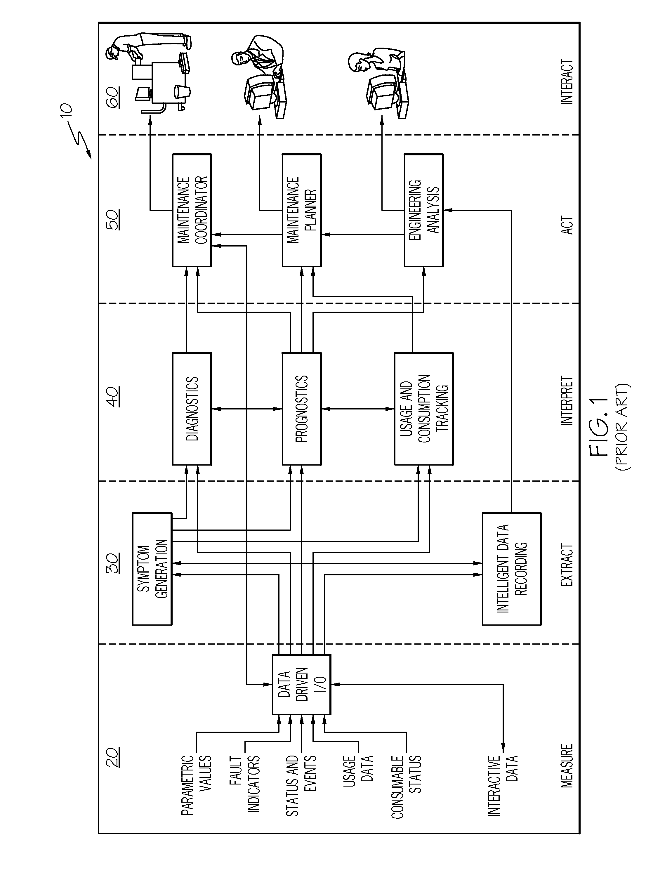
TECHNICAL FIELD[0001]The present invention generally relates to architectures for condition based health maintenance systems, and more particularly relates to architectures that may be flexibly reconfigured by a user to reflect the physical structure of an asset being monitored and how the asset is being monitored.BACKGROUND[0002]Increases in vehicle complexity and the accompanying increase in maintenance costs have led to industry wide investments into the area of condition based health management (CBM). These efforts have led to the development of industry or equipment specific process solutions. However, conventional CBM systems are generally rigidly configured requiring the user to live with cumbersome performance or pay significant modification costs.[0003]FIG. 1 is a simplified block diagram of an exemplary multi-level health maintenance process 10 that may be useful in monitoring a complex system (not shown). A complex system as discussed herein may be any type of vehicle, ai...

Claims


Application Information

Patent Timeline
Patent Type & Authority Applications(United States)
IPC IPC(8): G06F9/00
CPCG05B23/0213
Inventor FELKE, TIMBELL, DOUGLAS ALLENBISHOP, DOUGLASVANDERZWEEP, JEFFALJANABI, ISSA
Owner HONEYWELL INT INC
Why Eureka
Try Eureka