Methods and systems for cyber-physical security modeling, simulation and architecture for the smart grid

a cyberphysical security and smart grid technology, applied in the field of complex system security, can solve problems such as lack of understanding, expansion of environmental footprint, and potential acceleration of climate change, and the end of the useful life of existing electrical grid infrastructures

Active Publication Date: 2013-08-01
THE BOEING CO
View PDF3 Cites 68 Cited by
  • Summary
  • Abstract
  • Description
  • Claims
  • Application Information

AI Technical Summary

Benefits of technology

[0004]In one aspect, a computer-implemented method for use in evaluating at least one threat to a complex system includes identifying one or more physical components of the complex system and modeling the one or more physical components with interactive software multi-agents. The multi-agents are programmed to monitor and control at least one function of the modeled physical components. One or more threats to a target of the complex system are identified. Each threat is defined as a cyber attack or physical attack on a target, which is defined as a cyber component or physical component. The method includes simulating an attack on the complex system by the identified threat and assessing an impact of the attack on the complex system.
[0005]In another aspect, a non-transitory computer-readable medium storing program includes instructions for use in evaluating at least one threat for a complex system. The instructions cause the processor to identify one or more physical components of the complex system and model the one or more physical components with interactive software multi-agents, the multi-agents programmed to monitor and control at least one f...

Problems solved by technology

However, most of the existing electrical grid infrastructures are either close to their end of their useful life and/or dependent upon depleting non-renewable energy resources.
Further, electricity generation generates several million tonnes of carbon dioxide (CO2) emissions, which may over time expand the environmental footprint and potentially accelerates climate change.
However, there is lack of understanding of h...

Method used


Image

  • Methods and systems for cyber-physical security modeling, simulation and architecture for the smart grid
  • Methods and systems for cyber-physical security modeling, simulation and architecture for the smart grid
  • Methods and systems for cyber-physical security modeling, simulation and architecture for the smart grid

Examples


Embodiment Construction

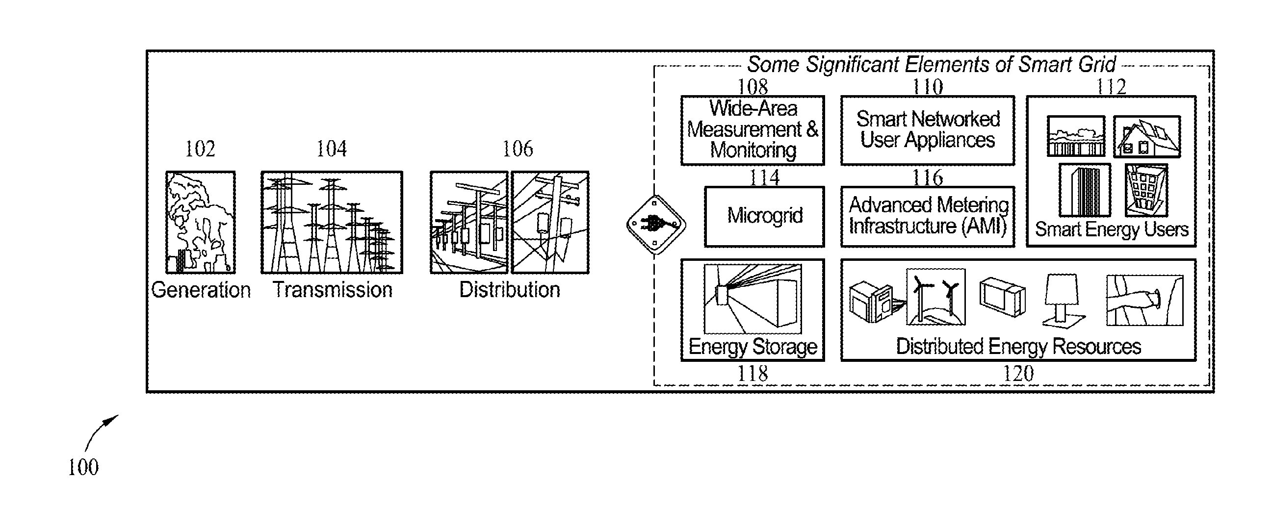
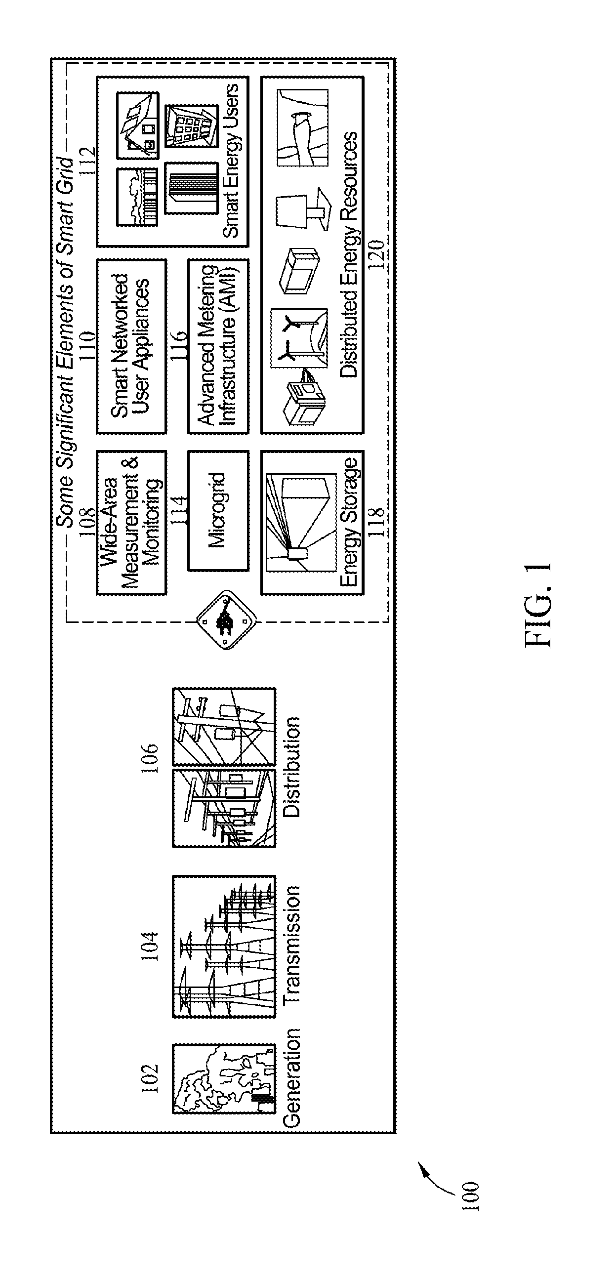
[0014]Shown generally in FIG. 1 is an exemplary smart grid 100. Elements of smart grid 100 include power generation component 102, power transmission component 104, and power distribution component 106. In some embodiments, smart grid 100 includes one or more of a wide-area measuring and monitoring component 108, smart networked user appliances 110, smart energy users 112, a microgrid 114, advanced metering infrastructure (AMI) 116, an energy storage component 118, and distributed energy resources (DER) 120. In one embodiment, DER 120 includes one or more microturbines, combustion turbines, reciprocating engines, sterling engines, fuel cells, photovoltaic systems, wind systems, hybrid systems, combined heat and power (CHP) and the like. In some embodiments, energy storage components 118 include one or more batteries, flywheels, supercapacitors, superconducting magnetic storage and compressed air storage. In another embodiment, microgrid 114 is a system connecting two or more DER sys...


PUM


Abstract

A computer-implemented method for use in evaluating at least one threat to a complex system includes identifying one or more physical components of the complex system and modeling the one or more physical components with interactive software multi-agents. The multi-agents are programmed to monitor and control at least one function of the modeled physical components. One or more threats to a target of the complex system are identified. Each threat is defined as a cyber threat or physical threat and the target is defined as a cyber component or physical component. The method includes simulating an attack on the complex system by the identified threat and assessing an impact of the attack on the complex system.

Description

BACKGROUND [0001]The field of the disclosure relates generally to complex-system security, and more particularly, to methods and systems for cyber-physical security modeling, simulation and architecture for complex systems, such as smart grids.[0002]The United States typically requires over 475 GWh of electricity per hour. That minimum demand level is expected to increase by at least about 30% before year 2030. However, most of the existing electrical grid infrastructures are either close to their end of their useful life and / or dependent upon depleting non-renewable energy resources. Further, electricity generation generates several million tonnes of carbon dioxide (CO2) emissions, which may over time expand the environmental footprint and potentially accelerates climate change. Electricity rates are also forecasted to increase by at least about 50% before year 2015. Stakeholders in this aging grid include utilities, technology providers, regulators, policy makers, environmental gr...

Claims


Application Information

Patent Timeline
IPC IPC(8): G06F21/00
CPCH04L63/1433H04L63/14Y04S40/24Y04S40/20
Inventor SAMPIGETHAYA, RADHAKRISHNA G.
Owner THE BOEING CO
Why Eureka
Try Eureka