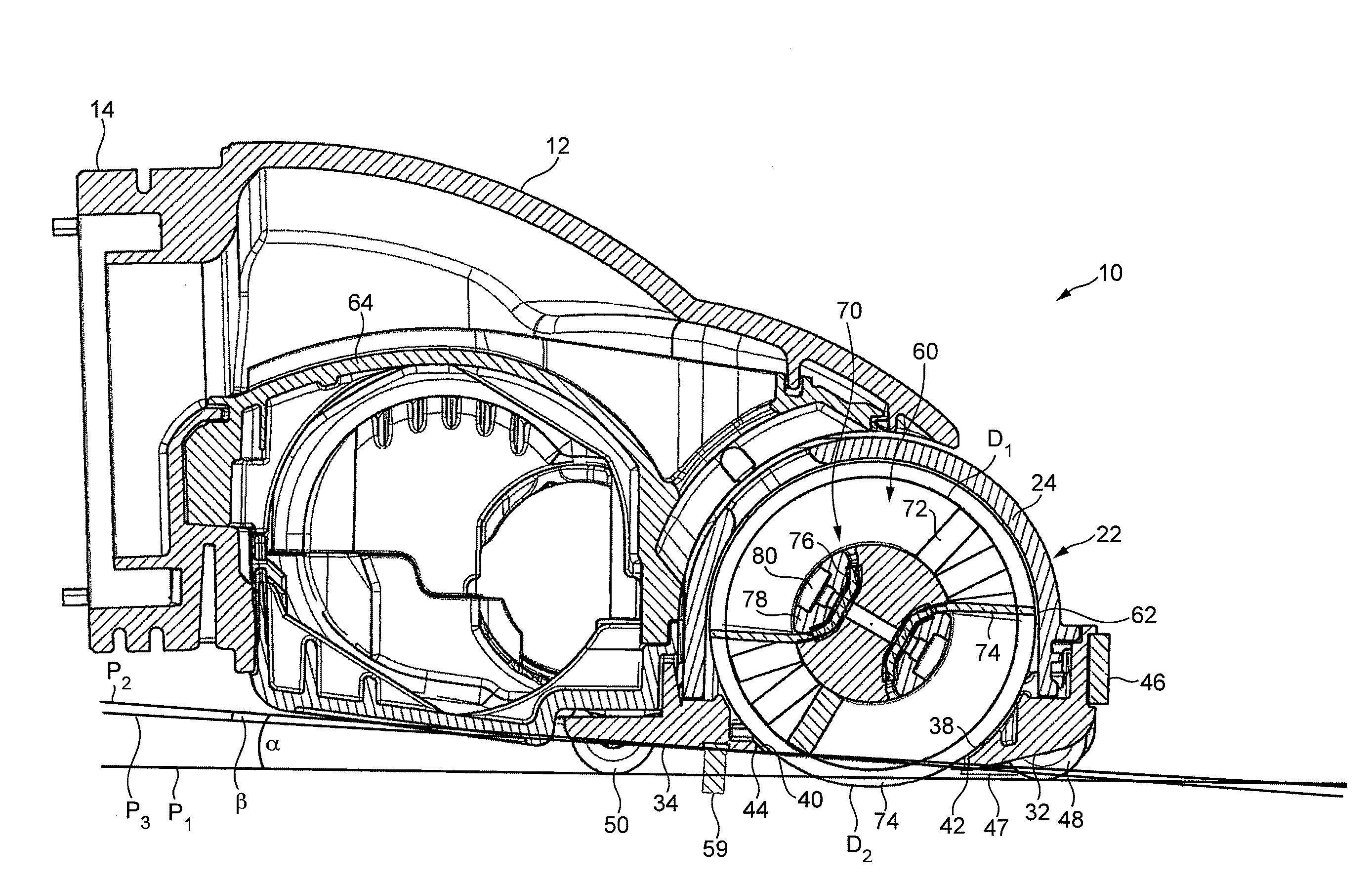
[0011]The opening of the sole plate, which extends between the front and rear edges, is thus located within a second plane which is inclined upwardly relative to a first plane containing the lowermost extremities of the support members. As a result of the inclination of the second plane relative to the first plane, the
central region of the opening, from which the agitating means tend to protrude by the greatest extent, can be raised above the first plane by a distance which is greater than when the second plane is parallel to the first plane (and while maintaining the same distance between the first plane and the
front edge of the opening). This allows the distance by which the agitating means may protrude through the opening, while still within the constraint that the agitating means do not extend beyond the first plane, to be increased, thereby facilitating the manufacture of the cleaner head.
[0012]The extent of this increase in the distance by which the agitating means may protrude from the opening depends on the width of the opening, as measured between the front and rear edges of the opening, and the angle between the first plane and the second plane. The width of the opening is preferably between 20 and 40 mm. An angle subtended between the first plane and the second plane is preferably less than 10°, and is more preferably less than 5°. For example, in a preferred embodiment the width of the opening is around 25 mm, and the angle between the first plane and the second plane is around 3°. This allows the agitating means to protrude through the opening by a distance of around 1.5 mm without extending beyond the first plane. In additional to relaxing the manufacturing tolerances, this can allow improve the cleaning performance of the cleaner head on a carpeted floor surface by increasing the penetration of the agitating means between the fibers of the carpet; when the cleaner head is located on a carpet, the support members will sink between the fibers of the carpet to bring the rear edge of the opening into contact with the surface of the carpet.
[0013]The sole plate is preferably pivotable relative to the agitator chamber to move the rear edge of the opening into contact with the surface of the carpet as the support members sink between the fibers of the carpet. For example, the sole plate may be pivotably connected to a main body of the cleaner head which defines the agitator chamber. As the cleaner head is pulled backwards over a carpeted floor surface by a user, there is a tendency for the user to raise the rear of the cleaner head, and so this pivoting movement of the sole plate also allows the edges of the opening to be kept in contact with this floor surface during cleaning. This can enable a seal to be maintained between the edges of the opening and the floor surface during cleaning, which can improve the pick up performance of the cleaner head. The sole plate is preferably pivotable relative to the agitator chamber about a pivot axis which is substantially parallel to the
front edge of the opening.
[0015]The angle subtended between the first plane and the second plane is preferably relatively small to minimize the distance between the first plane and the rear end of the trailing section of the sole plate. For example, in the aforementioned embodiment the rear end of the trailing section of the sole plate may be raised by a distance of around 3 to 4 mm from the first plane. To improve the performance of the cleaner head when it is located on a hard floor surface, the cleaner head preferably comprises flexible surface engaging means extending downwardly from the trailing section of the sole plate for forming a seal with the surface on which the cleaner head is located. The surface engaging means preferably extends along substantially the entire length of the trailing section, preferably adjacent to the rear edge of the opening and between the rear edge and the support member(s) located on the trailing section of the sole plate. The surface engaging means may comprise a strip of flexible material, or a row of bristles. The bristles may be formed from nylon, and are preferably relatively flexible in order to allow the bristles to deform readily to lie flat against the trailing section of the sole plate when the cleaner head is located on a carpeted floor surface so as not to disturb the seal formed between the sole plate and the surface of the carpet and to present only a
low resistance to motion of the cleaner head over the carpet.
[0016]The bottom surface of the other section of the sole plate, which in the aforementioned embodiment is the leading section of the sole plate, is preferably inclined to the second plane. The bottom surface of the other section of the sole plate may be located in a plane which is substantially parallel to the first plane, but it is preferably located in a plane which is inclined upwardly relative to the first plane. This allows the leading section to guide the fibers of a rug or deeply piled carpeted floor surface beneath the cleaner head and into the opening as the cleaner head is maneuvered forwardly over that floor surface, thereby lowering the resistance to forward motion of the cleaner head over the floor surface.
[0019]The second agitating means may be formed from material having a lower
surface resistivity than that from which the first agitating means is formed. This can inhibit charging of a hard floor surface with
static electricity upon contact with the second agitating means. This allows fine dust and
powder which would otherwise be attracted to the floor surface to be dislodged from the floor surface by the second agitating means.

