Aerodynamic projectile

Inactive Publication Date: 2012-08-09
PC IP GROUP
View PDF4 Cites 29 Cited by
  • Summary
  • Abstract
  • Description
  • Claims
  • Application Information

AI Technical Summary

Benefits of technology

[0014]According to another embodiment, the sidewall member has an inner surface and an outer surface, and a first end and a second end. The inner surface of the sidewall member and a second surface of the cross member form the rear open cavity opposing the front closed cavity of the generally hemispherical member. The rear open cavity is generally open at the second end of the sidewall and assists in decreasing the weight of the shell to assist in maintaining the center of gravity of the projectile in front of the center of pressure of the projectile during the flight of the projectile. One means to maintain the center of gravity in front of the center of pressure during flight of the projectile is the have the proper ration of shell weight and fill weight. The sidewall member may comprise a variety of geometric configurations, such as cylindrical or frustoconical.
[0015]According to another embodiment, a plurality of fins extend from the outer surface of the sidewall member. In such an embodiment the radially extending fins preferably provide a generally outer cylindrical circumference for the sidewall member having approximately the same diameter as the generally hemispherical member. In one embodiment the fins are orientated at an angle to a plane of the sidewall member. In another embodiment the

Problems solved by technology

Rubber bullets, however, have their drawbacks.
For example, rubber bullets can penetrate the skin causing severe injury to the target.
Additionally, rubber bullets are poor projectiles for marking a target.
However, such paint balls have several drawbacks.
For example, because the typical paint ball is made of a gelatinous material it cannot be filled with a wide variety of components, such as aqueous pigments and/or dyes.
While such plastic paint balls effectively mark a target without injury and do not have the drawback of limiting the type of material that can be carried in the paint ball, they may not adequately stun or immobilize a target, as is needed for the purpose of riot control.
More importantly, traditional paint balls, whether the shell is formed from gelatin or plastic, suffer from inaccuracy, especially when launched from a distance greater than 100 feet from the target.
This inaccuracy is due, in part, to the spherical shape and smooth surface of the paint ball proje

Method used


Image

  • Aerodynamic projectile
  • Aerodynamic projectile
  • Aerodynamic projectile

Examples


Example

[0027]While this invention is susceptible of embodiments in many different forms, there is shown in the drawings and will herein be described in detail preferred embodiments of the invention with the understanding that the present disclosure is to be considered as an exemplification of the principles of the invention and is not intended to limit the broad aspect of the invention to the embodiments illustrated.

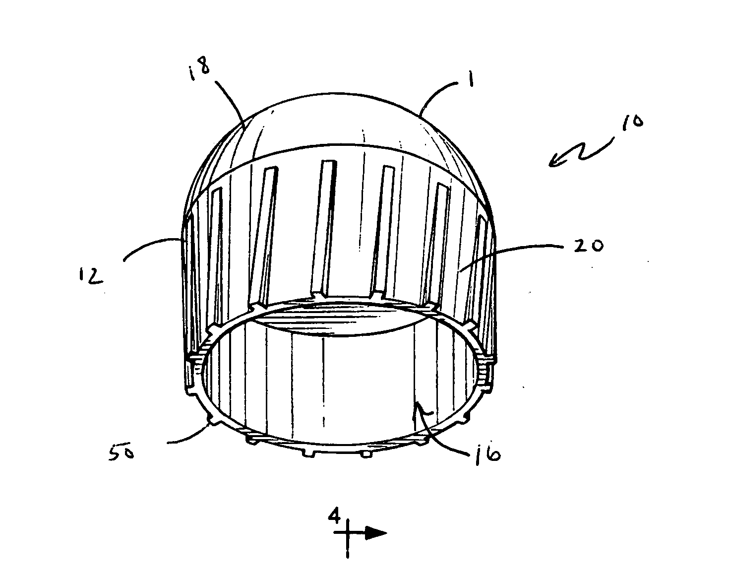
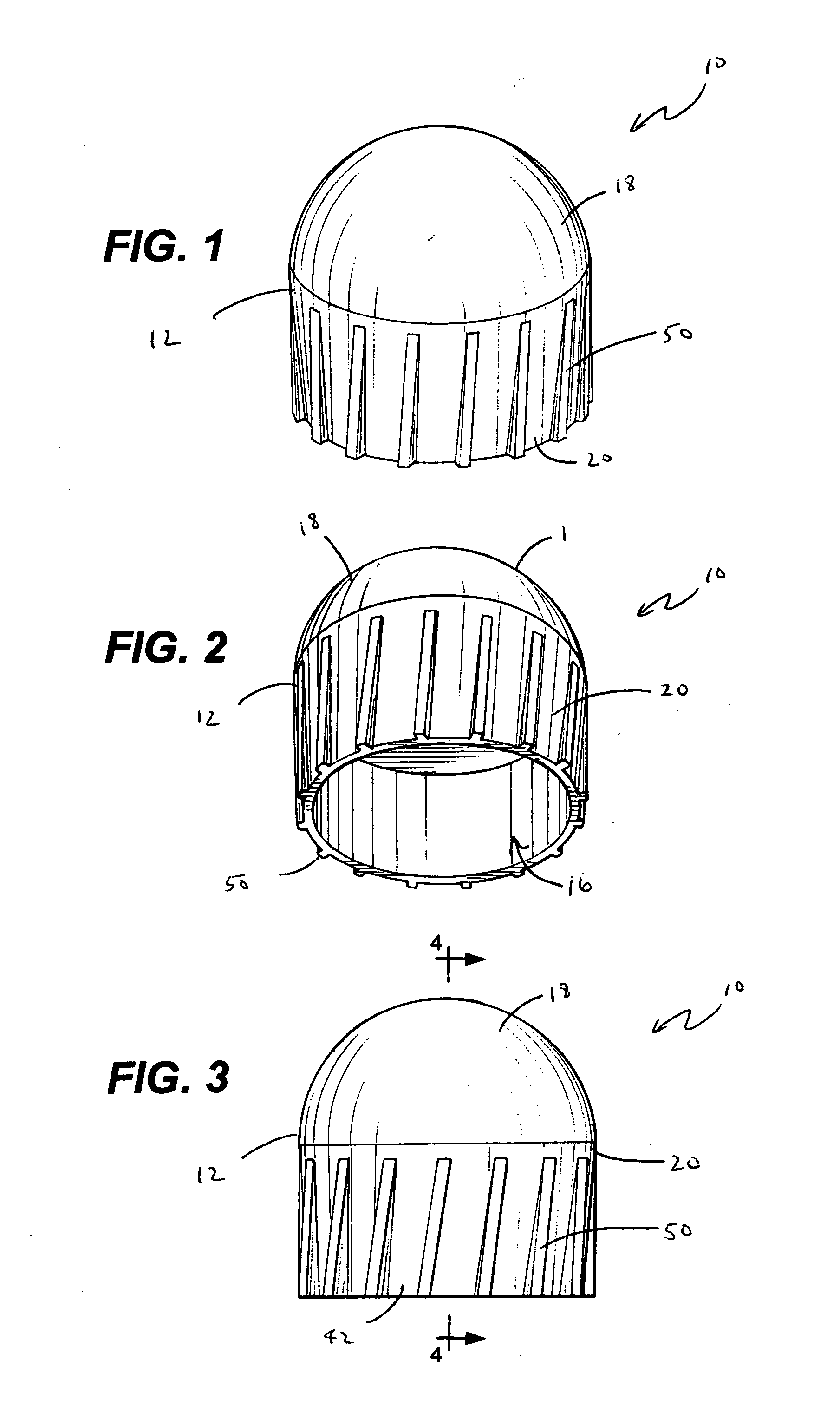
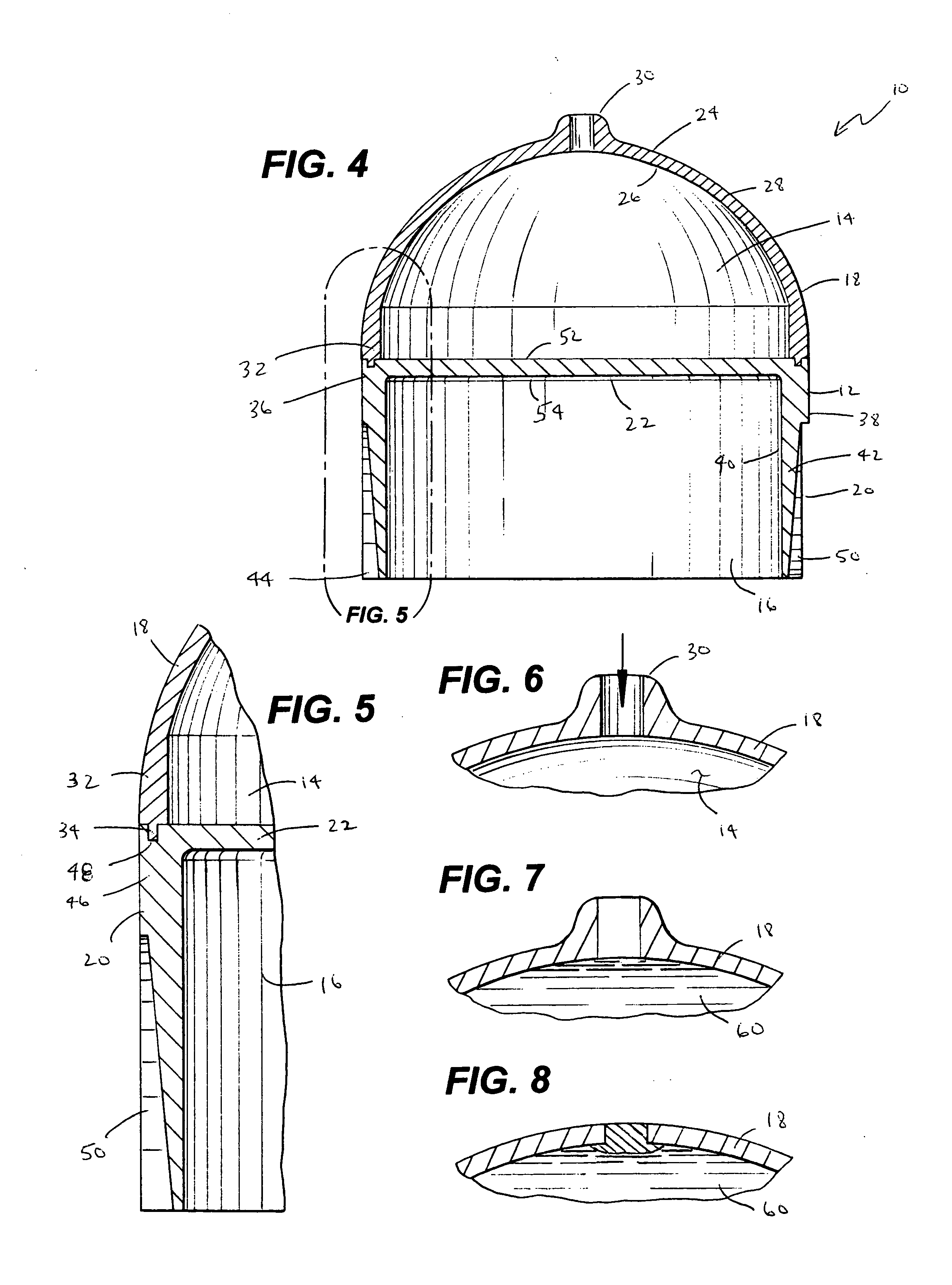
[0028]Referring now to the Figures, and specifically to FIGS. 1-4, there is shown an aerodynamic projectile 10 for carrying a payload, and which is suitable for less lethal uses, including recreational play. The aerodynamic projectile 10 generally comprises a shell 12 having a first front closed cavity 14 and a second open rear cavity 16. Preferably, the shell 12 of the aerodynamic projectile 10 fractures upon impact and is used to mark a target. In one embodiment the projectile 10 may be fired from generally available compressed gas guns such as paint ball guns. Accordingly, i...


PUM


Abstract

An aerodynamic projectile is provided having a shell with an aerodynamic structure and a controlled center of gravity, and which exhibits improved aerodynamics and resulting accuracy, and which is suitable for less lethal uses. The projectile shell has a closed front cavity housing a payload, such as a marking agent, therein. The projectile shell also has an open rear portion to provide access to the open rear cavity, and to decrease the weight of the projectile and appropriately locate the center of gravity. The projectile shell also includes a plurality of fins on a sidewall member to enhance the accuracy of the projectile.

Description

CROSS-REFERENCE TO RELATED APPLICATIONS[0001]Not applicable.FEDERALLY SPONSORED RESEARCH OR DEVELOPMENT[0002]Not Applicable.TECHNICAL FIELD[0003]The present invention relates generally to aerodynamic projectiles, and more particularly to aerodynamic projectiles having a closed front cavity and an open rear cavity, and which are suitable for non-lethal uses.BACKGROUND OF THE INVENTION[0004]A variety of non-lethal projectiles are known in the prior art. One type of non-lethal projectile is a rubber bullet that is typically used for the purpose of riot control. Rubber bullets, however, have their drawbacks. For example, rubber bullets can penetrate the skin causing severe injury to the target. Additionally, rubber bullets are poor projectiles for marking a target.[0005]Another type of non-lethal projectile is a paint ball. Paint balls are typically used for purposes of marking, such as to mark individuals for future identification without causing injury. Such non-lethal projectiles are...

Claims


Application Information

Patent Timeline
IPC IPC(8): F42B12/40F42B12/72F42B10/04
CPCF42B12/40F42B10/06
Inventor GIBSON, GARY E.VARACINS, MICHAEL A.
Owner PC IP GROUP
Why Eureka
Try Eureka