Anti-vibration device and binocle

a technology of anti-vibration and binoculars, which is applied in the direction of dynamo-electric components, dynamo-electric machines, instruments, etc., can solve the problems of difficult to reduce weight and size, and the inability to perform appropriate observation or imaging, so as to achieve smooth movement of reflective members and holding members

Active Publication Date: 2021-05-11
FUJIFILM CORP
View PDF8 Cites 0 Cited by
  • Summary
  • Abstract
  • Description
  • Claims
  • Application Information

AI Technical Summary

Benefits of technology

[0007]In the optical observation device such as the binocle, in order to correct image blurring of an observation image, an anti-vibration optical system is used. The anti-vibration optical system is built into the observation device, and therefore it is preferable that the anti-vibration optical system has a small size and a light weight in order to secure a storage space, increase a response speed, and improve portability. However, four reflective members are necessary for the anti-vibration optical system of JP1998-333201A (JP-H10-333201A), and an optical path is also elongated by the number of reflective members. Thus, it is difficult to decrease a weight and a size thereof.
[0009]Thus, the present inventors have developed an anti-vibration device capable of reducing the number of reflective members by performing anti-vibration in the pitch direction while one reflective member of the first reflective member and the second reflective member is fixed and the other reflective member is rotated and performing anti-vibration in the yaw direction while a pair of left and right holding members that each holds the first reflective member and the second reflective member is disposed and the holding members are rotated. However, such an anti-vibration device can reduce the number of reflective members, but needs to rotate the reflective members held by the holding members in order to perform the anti-vibration in the pitch direction while the holding members are rotated in order to perform the anti-vibration in the yaw direction. Accordingly, a device for smoothly performing both the anti-vibration in the yaw direction and the pitch direction so as not to hinder the linkage thereof.
[0016]According to the present invention, rotation amounts of a pair of holding members that is rotated around first rotational axes are equal to each other, and rotation amounts of the pair of other reflective members which are held by the pair of holding members and are rotated around second rotational axes are equal to each other. As a result, it is possible to smoothly move the reflective members and the holding members.

Problems solved by technology

Thus, it is difficult to decrease a weight and a size thereof.
However, this configuration has a problem in that a direction of the optical axis of the photography lens, along which light is incident into the anti-vibration optical system, is orthogonal to a direction of an optical axis of light emitted from the anti-vibration optical system.
Thus, there is a problem in that appropriate observation or imaging cannot be performed.

Method used


Image

  • Anti-vibration device and binocle
  • Anti-vibration device and binocle
  • Anti-vibration device and binocle

Examples


first embodiment

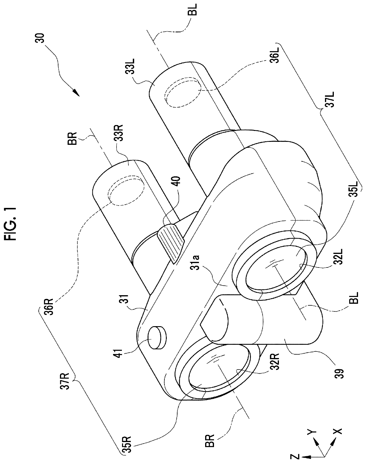
[0033]As shown in FIG. 1, a binocle 30 of the present embodiment is an optical observation device that is used to observe an optical image of a distant view in an enlarged manner through a pair of left telephoto optical system 37L and right telephoto optical system 37R which are constituted by telephoto optical systems.

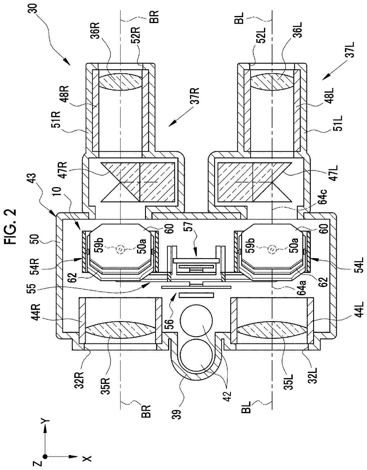
[0034]As shown in FIG. 2, an anti-vibration device 10 is provided in the left telephoto optical system 37L and the right telephoto optical system 37R of the binocle 30. Assuming that a front-back direction of the binocle 30 is a Y axis, a width direction orthogonal to the front-back direction is an X axis, and a vertical axis perpendicular to the Y axis and the X axis is a Z axis, the anti-vibration device 10 corrects image blurring in a pitch direction around the X axis and image blurring in a yaw direction around the Z axis.

[0035]As shown in FIG. 1, the binocle 30 includes a main body portion 31, and a pair of left eyepiece portion 33L and right eyepiece portion 33R...

second embodiment

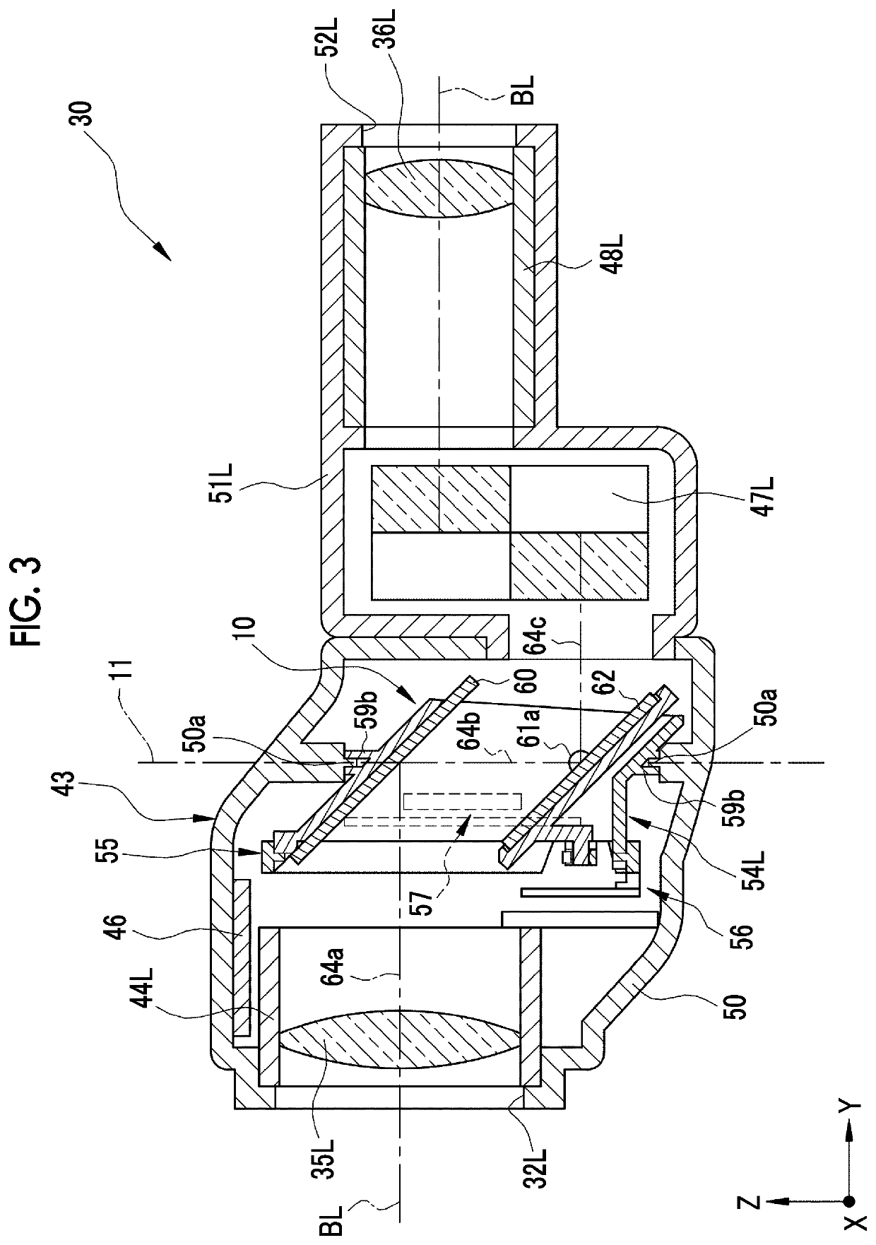
[0083]As shown in FIG. 4, in the first embodiment, the first reflective members 60 are inclined with respect to the first optical axes 64a of the objective optical systems at angles of 45°, and thus, the angle of the second optical axis 64b deflected with respect to the first optical axes 64a is set as 90°. In contrast, in a second embodiment shown in FIG. 16, the angle formed by the first optical axis 64a and the second optical axis 64b is smaller than 90°. Although not shown, the angle may be greater than 90°. Further, although it has been described in the first embodiment that the first rotational axis 11 and the second optical axis 64b are concentrically arranged with each other in a case where the barrels 59 that each hold the first reflective member 60 and the second reflective member 62 are integrally rotated, the present invention is not limited to thereto. For example, like a first rotational axis 19 represented by a dashed double-dotted line, the first rotational axis 19 c...


PUM


Abstract

Barrels are attached so as to be rotated around first rotational axes. Reflective members are fixed to the barrels, and reflective members are attached so as to be rotated around second rotational axes. Rotation amounts are equal to each other in rotation of the pair of left and right barrels around the first rotational axes and rotation of the reflective members of the barrels around the second rotational axes due to a link mechanism having a first link member and a second link member. Image blurring in a yaw direction is corrected due to movement of the first link member in an X axis direction. Image blurring in a pitch direction is corrected due to movement of the second link member in a Y axis direction.

Description

CROSS-REFERENCE TO RELATED APPLICATIONS[0001]This application is a Continuation of PCT International Application No. PCT / JP2016 / 084470 filed on 21 Nov. 2016, which claims priority under 35 U.S.C § 119(a) to Japanese Patent Application No. 2015-253274 filed on 25 Dec. 2015. The above application is hereby expressly incorporated by reference, in its entirety, into the present application.BACKGROUND OF THE INVENTION1. Field of the Invention[0002]The present invention relates to an anti-vibration device and a binocle which prevent image blurring of an optical image.2. Description of the Related Art[0003]Monocles each having a single telephoto optical system, binocles each having a pair of telephoto optical systems arranged in the left-right direction, and the like are known as an optical observation device for observing an optical image of a distant view in an enlarged manner. Further, in order to prevent image blurring of an optical image from being caused by vibration such as hand sha...

Claims


Application Information

Patent Timeline
Patent Type & Authority Patents(United States)
IPC IPC(8): G02B27/64G02B23/18G02B23/02H02K41/035
CPCG02B27/646G02B23/02G02B23/18H02K41/0356
Inventor KAYA, AKIMASAAWAZU, KOUHEI
Owner FUJIFILM CORP
Why Eureka
Try Eureka