
Cross member of vehicle body and method of manufacturing cross member

Active Publication Date: 2020-01-23
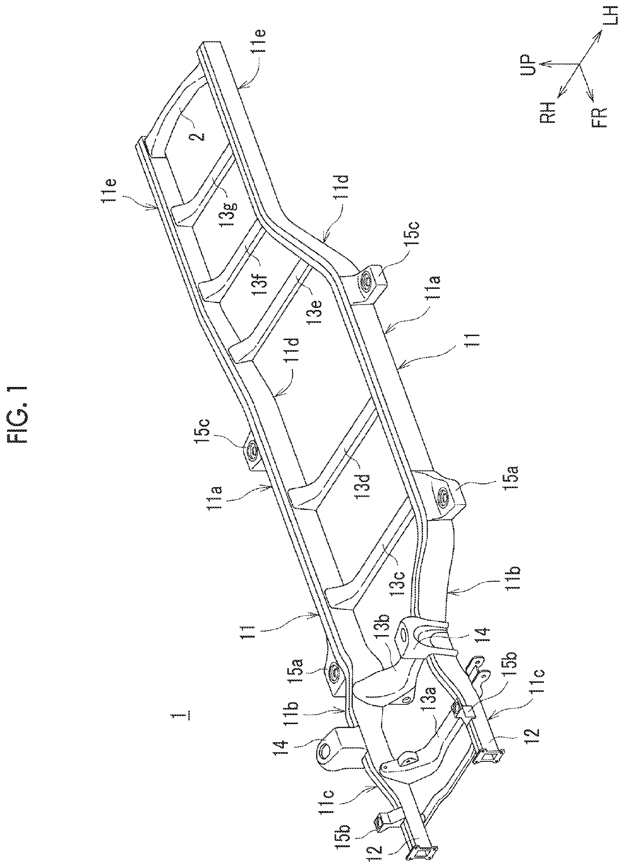
TOYOTA JIDOSHA KK
View PDF0 Cites 1 Cited by
  • Summary
  • Abstract
  • Description
  • Claims
  • Application Information

AI Technical Summary

Benefits of technology

The patent text describes a method for reducing the weight of a cross member used in a structure, such as a vehicle. The method involves integrally welding multiple panel members together, which differ in plate thickness dimensions. By doing this, the method achieves a decrease in weight, simplifies the structure, reduces manufacturing costs, and reduces heat damage and rust. Additionally, the method includes using a plate member with a level difference and cut mark to further reduce the thickness of the cross member.

Problems solved by technology

Therefore, there is a limit in decreasing the weight of the cross member to achieve a decrease in vehicle body weight.
However, in a case where the cross member a is manufactured as described above, the number of components is large and thus there is a possibility that the structure becomes complicated.
In addition, since it is necessary to perform welding on a plurality of points, there is a possibility of an increase in manufacturing cost, heat damage of a welding point (decrease in strength of welding point), and rust (rust in vicinity of welding point).
Therefore, a stress at connection portions between the cross member and the side rails is likely to become great at the time of towing due to the influence of a moment or the like applied to the connection portions.

Method used


Image

  • Cross member of vehicle body and method of manufacturing cross member
  • Cross member of vehicle body and method of manufacturing cross member
  • Cross member of vehicle body and method of manufacturing cross member

Examples


embodiment

Effect of Embodiment

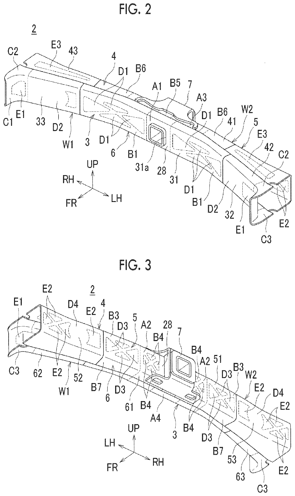
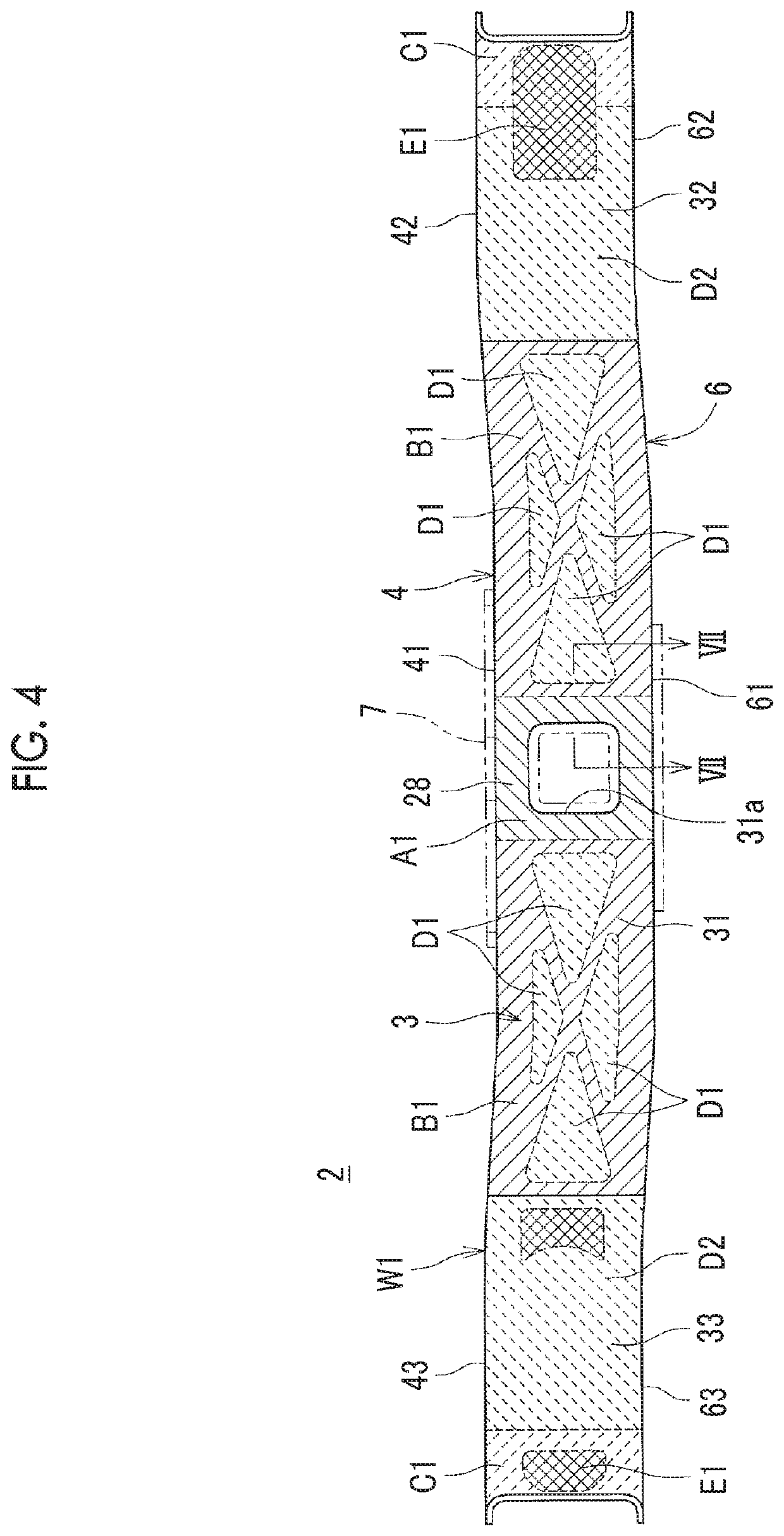
[0107]As described above, in the present embodiment, the first surface of the plate member W (surface on inner side of closed sectional structure) 21 is provided with the level difference portions 22, 23 and the second surface (surface on outer side of closed sectional structure) 24 is provided with the cut mark portion 25 such that a single plate member W is provided with a thick plate portion and a thin plate portion. That is, when manufacturing the rear cross member 2 by using the plate member W, it is possible to configure a portion of the rear cross member 2, to which a particularly large load is applied, as the thick plate portion and to configure a portion of the rear cross member 2, to which a relatively small load is applied, as the thin plate portion. Therefore, it is possible to achieve plate thickness dimensions corresponding to applied loads for a single plate member W. Specifically, the towing connection portion 28 provided in the central portion of...


PUM

PropertyMeasurementUnit
Thicknessaaaaaaaaaa
Widthaaaaaaaaaa

Abstract

A cross member includes a plate member. The plate member constitutes a portion of a vehicle body frame, extends in a vehicle width direction, and is formed of metal. The plate member is provided with a level difference portion on a first surface of the plate member, and a cut mark portion on a second surface of the plate member. The second surface is on the opposite side of the first surface of the plate member. The plate member is provided with a thick plate portion on a first side of the plate member in a direction in which the plate member extends, and a thin plate portion on a second side of the plate member in the direction in which the plate member extends, with the level difference portion interposed between the first and second sides.

Description

INCORPORATION BY REFERENCE[0001]The disclosure of Japanese Patent Application No. 2018-133866 filed on Jul. 17, 2018 including the specification, drawings and abstract is incorporated herein by reference in its entirety.BACKGROUND1. Technical Field[0002]The disclosure relates to a cross member of a vehicle body and a method of manufacturing the cross member. In particular, the disclosure relates to improvement of a cross member provided with a plurality of regions different from each other in plate thickness dimension.2. Description of Related Art[0003]In the related art, as a vehicle body frame of a vehicle, a structure (called frame structure) that is provided with a pair of right and left side rails (also called side frames) extending in a vehicle body front-rear direction and a cross member suspended between the side rails is known. Generally, the cross member is obtained by performing press working on a metal sheet material (high-tensile strength steel sheet or like) such that ...

Claims


Application Information

Patent Timeline
IPC IPC(8): B62D21/02B21D53/88B21D51/04
CPCB21D53/88B21D51/04B62D21/02B23P15/00B23P2700/50B62D21/09B21D22/02B21D47/01B62D21/03
Inventor ASAI, TETSUYAOKUMOTO, RYUICHI
Owner TOYOTA JIDOSHA KK
Learn More