Antenna device having membrane structure

Inactive Publication Date: 2008-08-14
WU HSIN HENG
View PDF2 Cites 0 Cited by
  • Summary
  • Abstract
  • Description
  • Claims
  • Application Information

AI Technical Summary

Benefits of technology

[0008]The primary objective of the present invention is to provide an antenna device including a membrane structure having a greatly reduced thickness for allowing the anten

Problems solved by technology

However, the antenna devices are normally made of metallic materials and should have or include a predetermined thickness and thus should include a predetermined weight such that the antenna devices also may not be easily attached onto various objects.
However, s

Method used


Image

  • Antenna device having membrane structure
  • Antenna device having membrane structure

Examples


Example

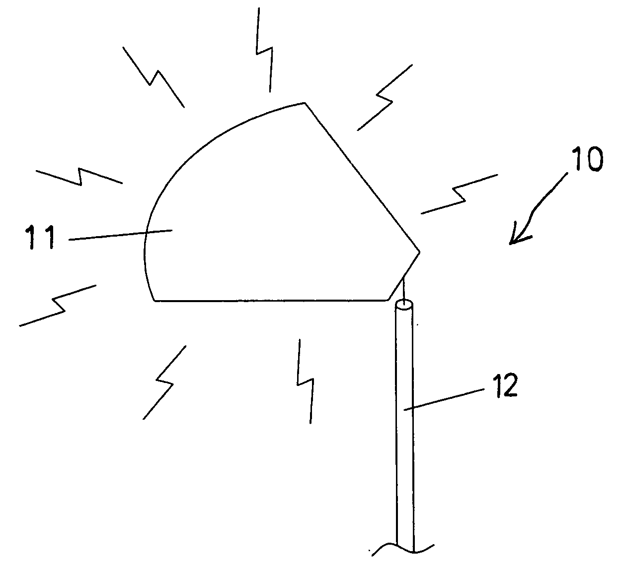
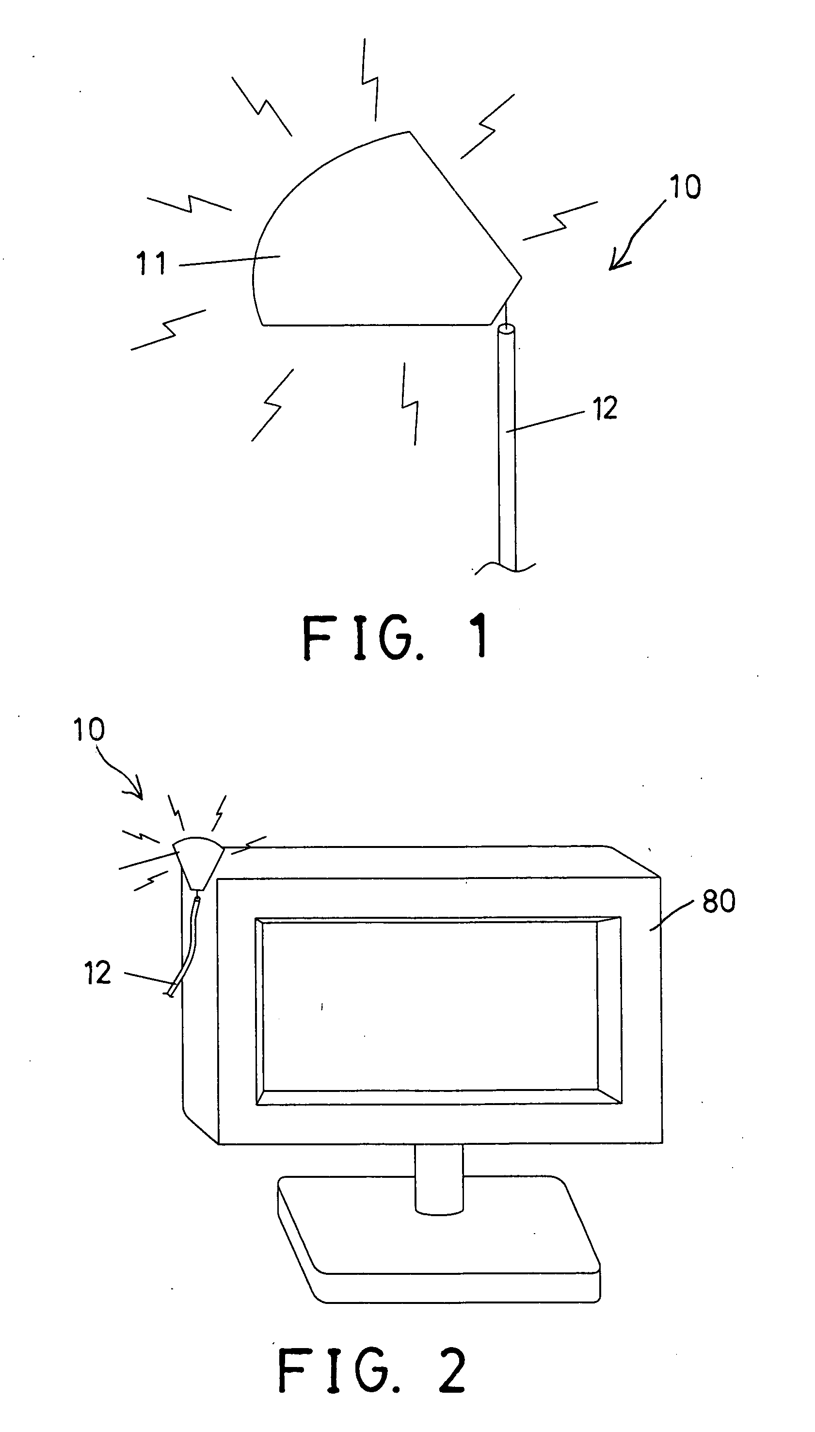
[0014]Referring to the drawings, and initially to FIG. 1, an antenna device 10 in accordance with the present invention comprises a membrane 11, and an electric wire or cable or conductor line or wire 12 coupled to the membrane 11 for electrically coupling the membrane 11 to various electric facilities or telecommunication apparatuses, such as computers, portable computers, personal digital assistants, portable or mobile phones, phone systems, radio and / or video facilities, global systems for mobile communications, vehicles, wireless network systems, etc.

[0015]The membrane 11 is preferably made of a metallic reflective material or layer that is provided for applied or attached onto various discs, such as VCD, DVD, CD, etc., and that includes a relative greater conductivity or dielectric coefficient, for allowing the membrane 11 to have a greater or excellent signal receiving and / or transmitting effect, or for facilitating the signal receiving and / or transmitting effect to the antenn...


PUM


Abstract

An antenna device includes a membrane, and a conductor wire coupled to the membrane for electrically coupling the membrane to various electric facilities or telecommunication apparatus, the membrane is preferably made of metallic reflective material that may be applied onto the typical compact discs and that includes a conductivity and dielectric coefficient for facilitating a signal receiving and transmitting effect to the antenna device. The membrane may include a flexible structure and attachable onto various objects to conform the outer contours of the objects.

Description

BACKGROUND OF THE INVENTION[0001]1. Field of the Invention[0002]The present invention relates to an antenna device, and more particularly to an antenna device having a membrane structure and having a greatly reduced thickness for allowing the antenna device to include a greatly decreased weight and to be easily attached onto various non-conductive materials.[0003]2. Description of the Prior Art[0004]Typical electric facilities or telecommunication apparatuses, such as computers, personal digital assistants, portable or mobile phones, phone systems, radio and / or video facilities, global systems for mobile communications, vehicles, wireless network systems, etc. comprise one or more antenna devices attached thereto for signal receiving and / or transmitting purposes.[0005]For allowing the antenna devices to be easily attached onto various objects, or to be easily carried with the users, the sizes or volumes or areas of the antenna devices have been reduced. However, the antenna devices ...

Claims


Application Information

Patent Timeline
IPC IPC(8): H01Q9/04
CPCH01Q9/40H01Q1/364
Inventor WU, HSIN HENG
Owner WU HSIN HENG
Why Eureka
Try Eureka