Electrical power distribution integrated into a satellite structural panel

Pending Publication Date: 2021-12-02
THALES SA
View PDF0 Cites 0 Cited by
  • Summary
  • Abstract
  • Description
  • Claims
  • Application Information

AI Technical Summary

Benefits of technology

[0020]Such a structural panel comprises a honeycomb layer: this is a very lightweight hexagonal cellular structure enclosed between two sheets of aluminium. The conductor placed between these walls is ideally shielded from an electromagnetic point of view, and consequently, larger high-freq

Problems solved by technology

The problem is intensified in space applications because the cables are in vacuum and therefore cooling takes place mainly by radiation.
This represents a not-insignificant onboard weight, the cost potential

Method used


Image

  • Electrical power distribution integrated into a satellite structural panel
  • Electrical power distribution integrated into a satellite structural panel
  • Electrical power distribution integrated into a satellite structural panel

Examples


Embodiment Construction

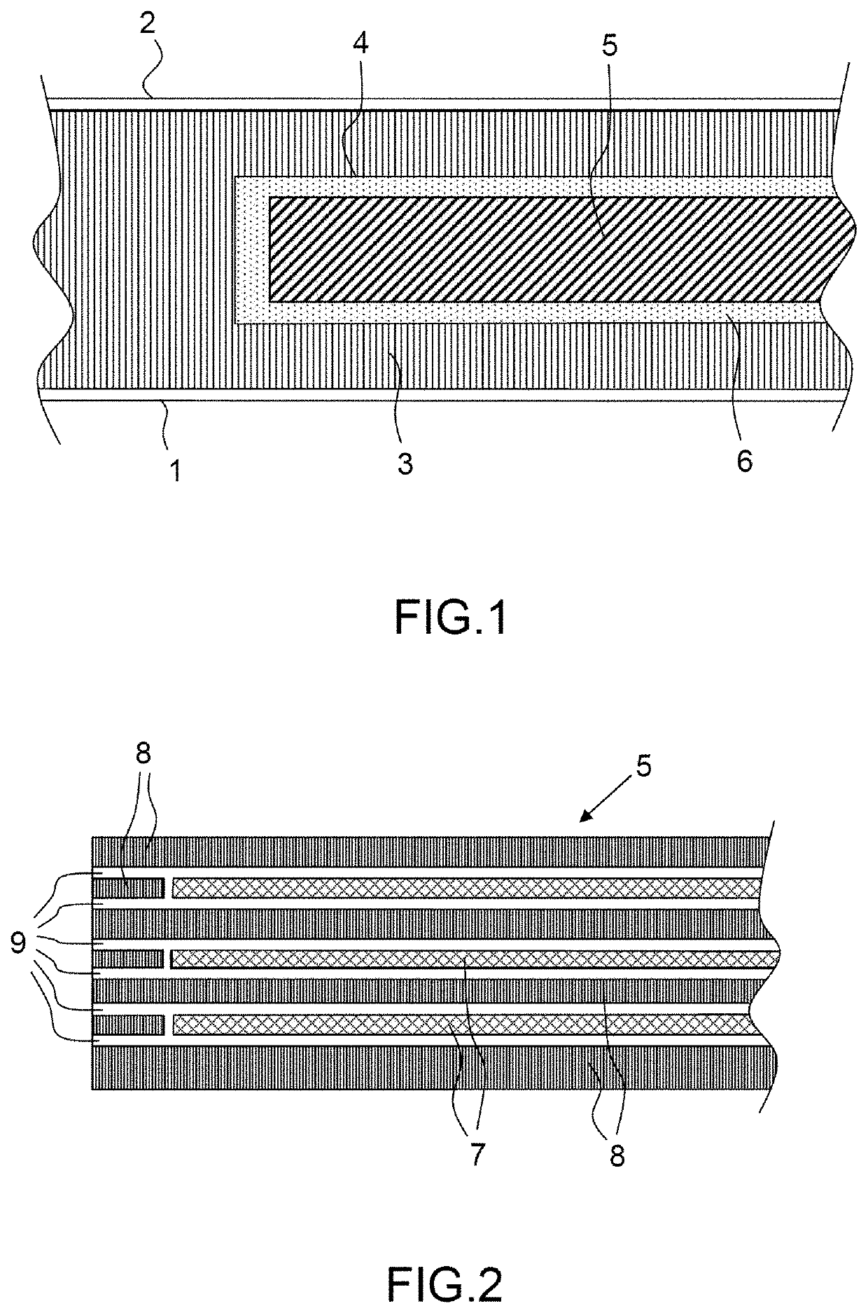
[0029]FIG. 1 shows, in cross section, a structural panel according to one aspect of the invention, comprising an external skin 1, which is for example electromagnetically shielded, intended to be on the outside of a satellite, an internal skin 2, which is for example electromagnetically shielded, intended to be on the inside of the satellite, and a core layer 3 arranged between the two, internal 2 and external 1, skins and provided with a blind void 4 comprising at least one inserted busbar 5. A joining material 6 fills the blind void 4 in order to keep the inserted busbar 5 fixed in place.

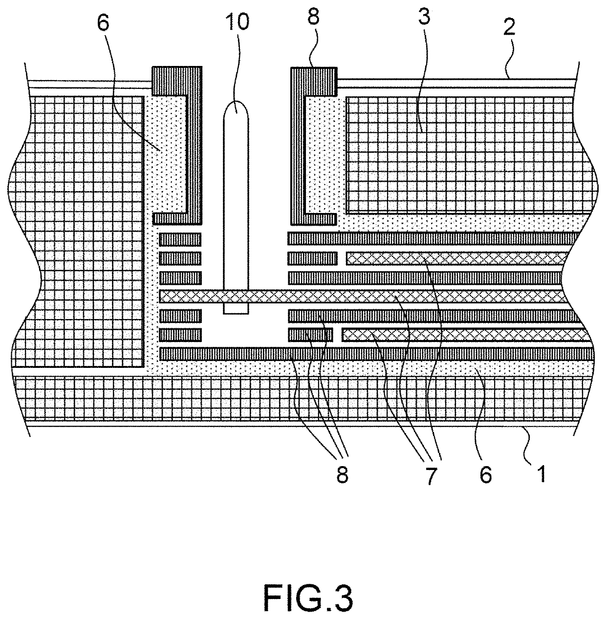
[0030]FIG. 2 shows, in cross section, the detail of a busbar 5 comprising a set of electrically conductive layers 7 and of electrically insulating layers 8 such that each conductive layer 7 is electrically insulated by an envelope formed of two electrically insulating layers 6. For example, the busbar 5 comprises three bars or conductive layers 7 that are electrically insulated by a respective env...


PUM

PropertyMeasurementUnit
Pressureaaaaaaaaaa
Electrical conductivityaaaaaaaaaa
Structureaaaaaaaaaa

Abstract

A structural panel for a satellite includes an external skin, an internal skin and a core layer arranged between the two, internal and external, skins and provided with a blind void comprising at least one electrically insulated inserted busbar.

Description

CROSS-REFERENCE TO RELATED APPLICATIONS[0001]This application claims priority to foreign European patent application No. EP 20305560.3, filed on May 28, 2020, the disclosure of which is incorporated by reference in its entirety.FIELD OF THE INVENTION[0002]The invention pertains to a structural panel for satellites and relates to the distribution of electrical power on board satellites. The exchange of electrical power between the batteries, the power conditioning unit and certain heavy consumers such as the payload takes place using electrical cables.BACKGROUND[0003]The distribution of the direct current between certain items of equipment of the satellite requires the parallel placement of numerous wires in order to be able to conduct the current with minimum losses and to limit heating.[0004]The problem is intensified in space applications because the cables are in vacuum and therefore cooling takes place mainly by radiation.[0005]Thus, the interior of satellites generally features...

Claims


Application Information

Patent Timeline
IPC IPC(8): B64G1/42
CPCB64G1/428B64G1/10B32B3/08B32B3/12B32B5/18B32B2307/202B32B2307/206
Inventor BEKEMANS, MARCVANDEPLASSCHE, PHILIPPEMABED, BARBARA
Owner THALES SA
Why Eureka
Try Eureka