Method for Centering an Optical Element in a TEM Comprising a Contrast Enhancing Element

a technology of contrast enhancement and optical elements, applied in the field of adjusting or aligning one or more optical elements in a transmission electron microscope (tem), can solve the problems of contamination, phase plate damage, low contrast of large structures, etc., and achieve the effect of enhancing the contrast transfer function

Active Publication Date: 2012-08-09
FEI CO
View PDF6 Cites 8 Cited by
  • Summary
  • Abstract
  • Description
  • Claims
  • Application Information

AI Technical Summary

Benefits of technology

[0013]The invention relates to a method for adjusting or aligning one or more optical elements in a Transmission Electron Microscope. The TEM equipped with an objective lens for guiding a beam of electrons to a sample shows a diffraction plane in which at least a beam of unscattered electrons is focused. The TEM is equipped with a structure to enhance the Contrast Transfer Function which is situated in the diffraction plane or an image thereof while irradiation with unscattered electrons of the structure during the adjusting or aligning is prevented by deflecting the beam of unscattered away from the structure.

Problems solved by technology

A problem of said imaging method is that for low spatial frequencies the Contrast Transfer Function (CTF) shows a minimum, and thus the contrast of large structures is low.
The phase plate may thus be damaged due to thermal heating, and also contamination may occur, said contamination giving rise to charging when irradiated.
Also beam induced oxidation may result in charging.
This may give rise to surface oxidation of the phase plate structure, and thus to charging.
It is noted that such damaging or contamination problems may also occur when other optical elements upstream of the phase plate (upstream meaning between electron source and the phase plate) are aligned, as this may cause a shift of the image in the diffraction plane.

Method used


Image

  • Method for Centering an Optical Element in a TEM Comprising a Contrast Enhancing Element
  • Method for Centering an Optical Element in a TEM Comprising a Contrast Enhancing Element
  • Method for Centering an Optical Element in a TEM Comprising a Contrast Enhancing Element

Examples


Embodiment Construction

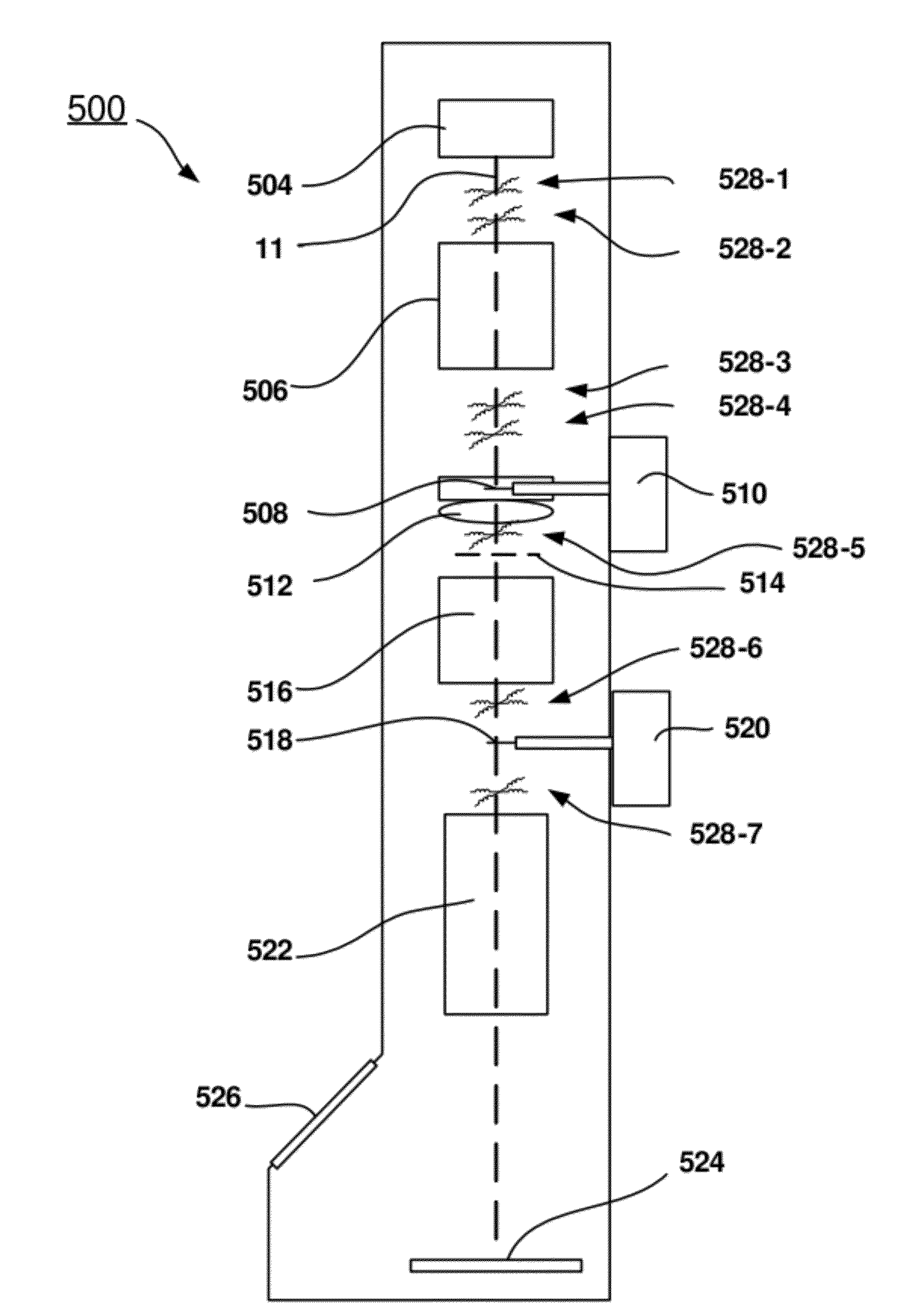
[0025]In accordance with some embodiments of the invention, a method for adjusting or aligning one or more optical elements in a TEM comprises preventing irradiation with unscattered electrons of the structure to enhance the CTF during the adjusting or aligning process by deflecting the beam of unscattered electrons away from the structure.

[0026]By deflecting the beam away from the structure, the structure is not irradiated, and thus charging, contamination and / or damage of the structure is prevented. It is noted that this may result in the irradiation of parts removed from the axis, but this is in most cases of less importance, as any contamination on these remote places intercept during normal use less electrons, and thus less charging occurs. A correction for some additional astigmatism is usually sufficient to eliminate the effect of charging of an aperture edge.

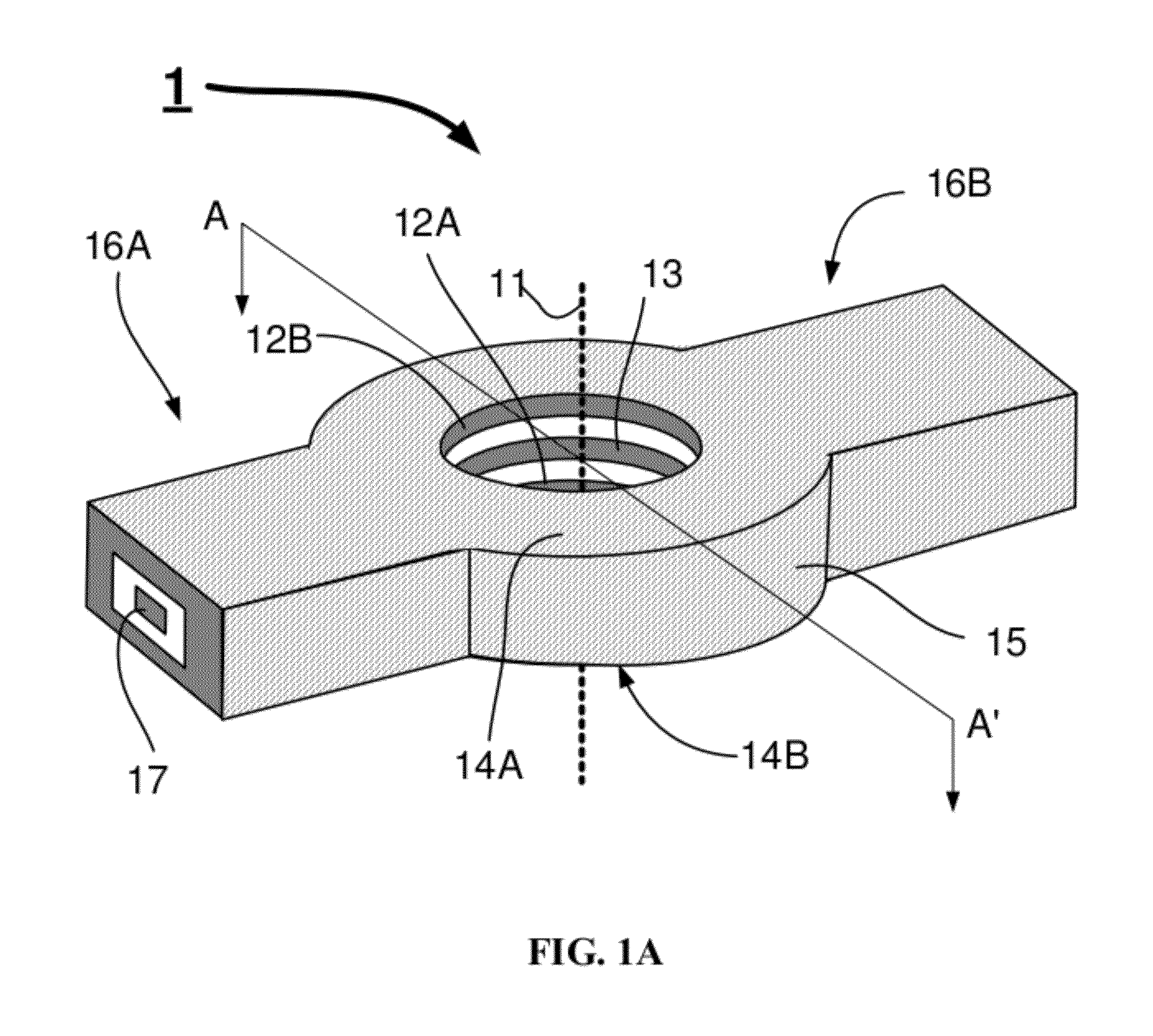
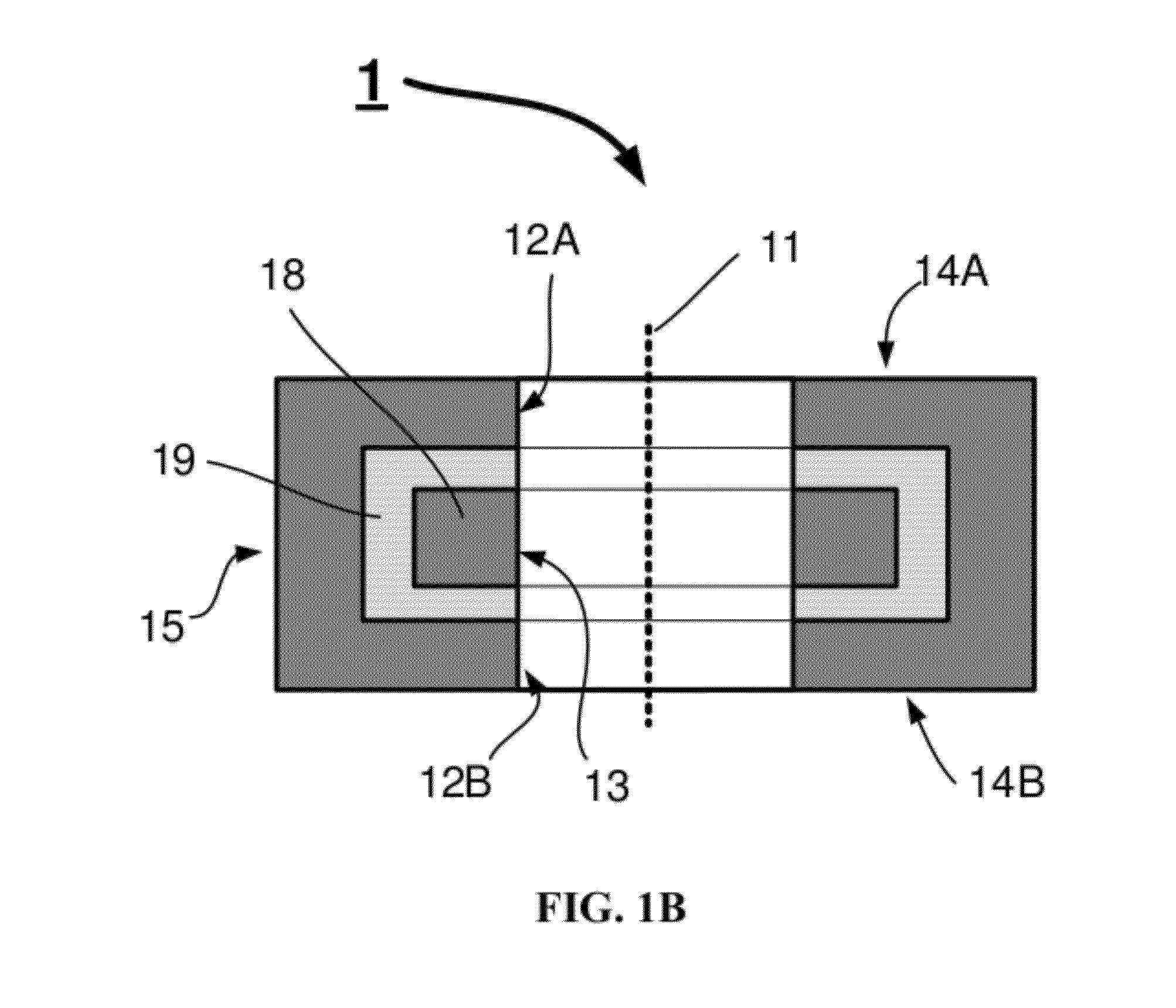
[0027]In some embodiments, the structure is a phase plate or a single sideband imaging device. Phase plates are known ...


PUM


Abstract

A method for adjusting or aligning one or more optical elements in a Transmission Electron Microscope (TEM) is disclosed. The TEM is equipped with an objective lens for guiding a beam of electrons to a sample, a diffraction plane in which at least a beam of unscattered electrons is focused and a structure to enhance the Contrast Transfer Function (CTF) which is situated in the diffraction plane or an image thereof.

Description

[0001]This Application claims priority from U.S. Provisional Application 61 / 440,113, filed Feb. 7, 2011, which is hereby incorporated by reference.TECHNICAL FIELD OF THE INVENTION[0002]The invention relates to a method for adjusting or aligning one or more optical elements in a Transmission Electron Microscope (TEM).BACKGROUND OF THE INVENTION[0003]Such a method is known from U.S. Pat. No. 6,744,048. This patent relates to aligning a phase plate in a TEM. In a TEM a beam of energetic electrons irradiates a thin sample. Preferably the beam is a parallel beam. The sample is so thin (typically between 25 nm and 250 nm), that most electrons pass through it unaffected, but some electrons are absorbed or scattered. In the diffraction plane (coincident with the back-focal plane of the objective lens when a parallel beam irradiates the sample) the electrons that passed the sample unhindered are all focused in one point. Scattered electrons are focused in other points in this diffraction pla...

Claims


Application Information

Patent Timeline
Patent Type & Authority Applications(United States)
IPC IPC(8): H01J3/26
CPCH01J37/26H01J2237/2614H01J2237/1501H01J37/265
Inventor BUIJSSE, BARTTIEMEIJER, PETER CHRISTIAANBIERHOFF, MARTINUS PETRUS MARIA
Owner FEI CO
Why Eureka
Try Eureka