Imprint apparatus and article manufacturing method

a technology of imprinting apparatus and manufacturing method, which is applied in the direction of photomechanical apparatus, manufacturing tools, instruments, etc., can solve the problems of insufficient pattern formation, large amount of time required for an imprinting step, and defect of pattern to be transferred, so as to achieve accurate pattern formation and throughput, and improve compatibility.

Inactive Publication Date: 2012-08-09
CANON KK
View PDF0 Cites 54 Cited by
  • Summary
  • Abstract
  • Description
  • Claims
  • Application Information

AI Technical Summary

Benefits of technology

[0007]The present invention provides an imprint apparatus that is adva...

Problems solved by technology

Because of the entrapped air bubbles (residual gas) in the resin, defects may occur on the pattern to be transferred.
Consequently, an accurate pattern may not be formed.
In contrast, a method for waiting until residual gas is dissolved into, diffused from, or passed through a resin or a mold to thereby be extinguished may exist, however, a considerable amount of time is required for an imprinting step.
However, in the imprint apparatuses disclosed in U.S. Pat. No. 7,090,716 and Japanese Patent No. 3700001, imprint atmosphere is totally purged by a permeable gas or a condensable gas, which is disadvantageous in terms of cost.
Thus, when the periphery of a resin on a substrate is purged by, for example, a gas having refractive index different from that of ambient a...

Method used


Image

  • Imprint apparatus and article manufacturing method
  • Imprint apparatus and article manufacturing method

Examples


Embodiment Construction

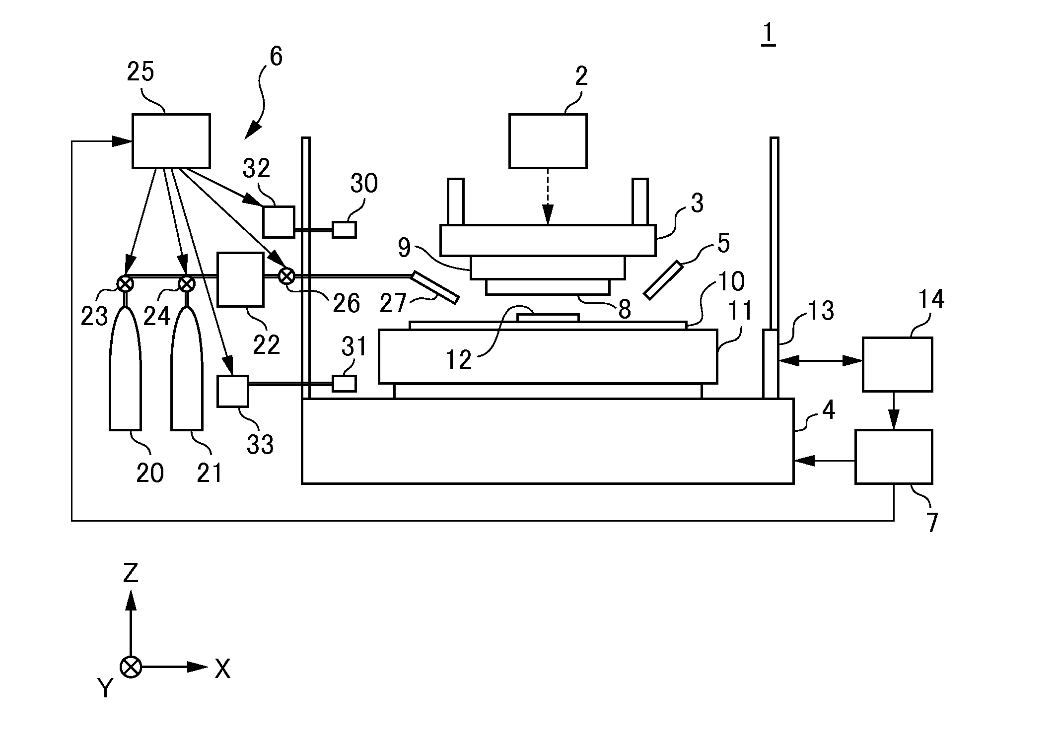
[0013]Hereinafter, preferred embodiments of the present invention will be described with reference to the drawings.

[0014]Firstly, a description will be given of the configuration of an imprint apparatus according to one embodiment of the present invention. FIG. 1 is a diagram illustrating the configuration of an imprint apparatus of the present embodiment. The imprint apparatus is an apparatus that molds an imprint material (typically, uncured resin) on a wafer (on a substrate), i.e., an object to be treated, using a mold to thereby form a pattern (typically, resin pattern) on the substrate, which is used in the manufacture of devices such as semiconductor devices and the like. Here, the imprint apparatus is an apparatus employing a photo-curing method. In the following drawings, a description will be given where the Z axis is aligned parallel to the optical axis of an illumination unit that illuminates ultraviolet light onto a resin on a substrate, and mutually orthogonal axes X an...


PUM

PropertyMeasurementUnit
Pressureaaaaaaaaaa
Ratioaaaaaaaaaa
Permeabilityaaaaaaaaaa

Abstract

An imprint apparatus of the present invention that molds and cures an imprint material on a substrate using a mold to form a pattern on the substrate. The imprint apparatus includes a supply unit configured to supply a gas into a gap between the imprint material on the substrate and the mold. The supply unit is configured to supply a mixed gas in which a permeable gas, which permeates at least one of the mold, the imprint material and the substrate, and a condensable gas, which is liquefied under a pressure generated by the molding, is mixed with each other.

Description

BACKGROUND OF THE INVENTION [0001]1. Field of the Invention[0002]The present invention relates to an imprint apparatus, and an article manufacturing method.[0003]2. Description of the Related Art[0004]As the demand for microfabrication of semiconductor devices increases, not only a conventional photolithography technology but also a microfabrication technology in which an uncured resin on a substrate is molded by a mold to thereby form a resin pattern on the substrate have been receiving attention. This technology is also referred to as an “imprint technology”, by which a fine structure with dimensions of a few nanometers can be formed on a substrate. One example of imprint technologies includes a photo-curing method. An imprint apparatus employing the photo-curing method first applies an ultraviolet curable resin (imprint resin, photocurable resin) to a shot area (imprint area) on a substrate (wafer). Next, the resin (uncured resin) is molded by a mold. After the ultraviolet curabl...

Claims


Application Information

Patent Timeline
IPC IPC(8): B29C59/02
CPCB82Y10/00B29C59/00G03F7/0002B82Y40/00B29C59/16B29C59/02B29C59/026B29C33/00B29C43/021B29C43/56B29C2043/566B29K2101/00B29L2031/34
Inventor TANABE, MASAYUKITAMURA, YASUYUKIHANYU, YUKIO
Owner CANON KK
Why Eureka
Try Eureka