Unit for a hydroelectric power plant and modular hydroelectric power plant comprising said unit

a hydroelectric power plant and hydroelectric technology, applied in conventional hydroenergy generation, couplings, electrical equipment, etc., can solve the problems of limiting the choice of possible sites for the installation of plants and affecting the construction cost of plants, and achieve the effect of sufficient speed

Inactive Publication Date: 2012-08-09
DEANDREA LUCA
View PDF8 Cites 11 Cited by
  • Summary
  • Abstract
  • Description
  • Claims
  • Application Information

AI Technical Summary

Benefits of technology

[0014]Thanks to the presence of a penstock comprising an inlet section and an outlet section, said outlet section being provided at least at 100 m depth and preferably at about 150-300 m depth wit

Problems solved by technology

Firstly, the requirement of a height difference between the basin and the turbines limits the choice of the possible sites for the installation of the plants.
Secondly, the need for the creation of an artificial basin strongly affects the construction costs of the plant.
Thirdly, the dams blocking the river gorges, block the solid transport of the rivers (sands and gravels) down to the sea where, because of the reduced or null solid deposit, there is the phenomenon of coast erosion. Finally, large hydroelectric basins can have environmental and socio-economic impacts of strong entity or gravity on the surrounding a

Method used


Image

  • Unit for a hydroelectric power plant and modular hydroelectric power plant comprising said unit
  • Unit for a hydroelectric power plant and modular hydroelectric power plant comprising said unit
  • Unit for a hydroelectric power plant and modular hydroelectric power plant comprising said unit

Examples


Embodiment Construction

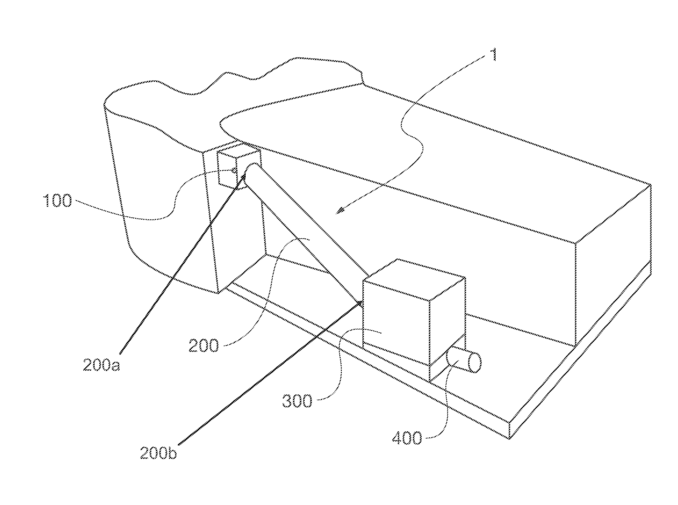
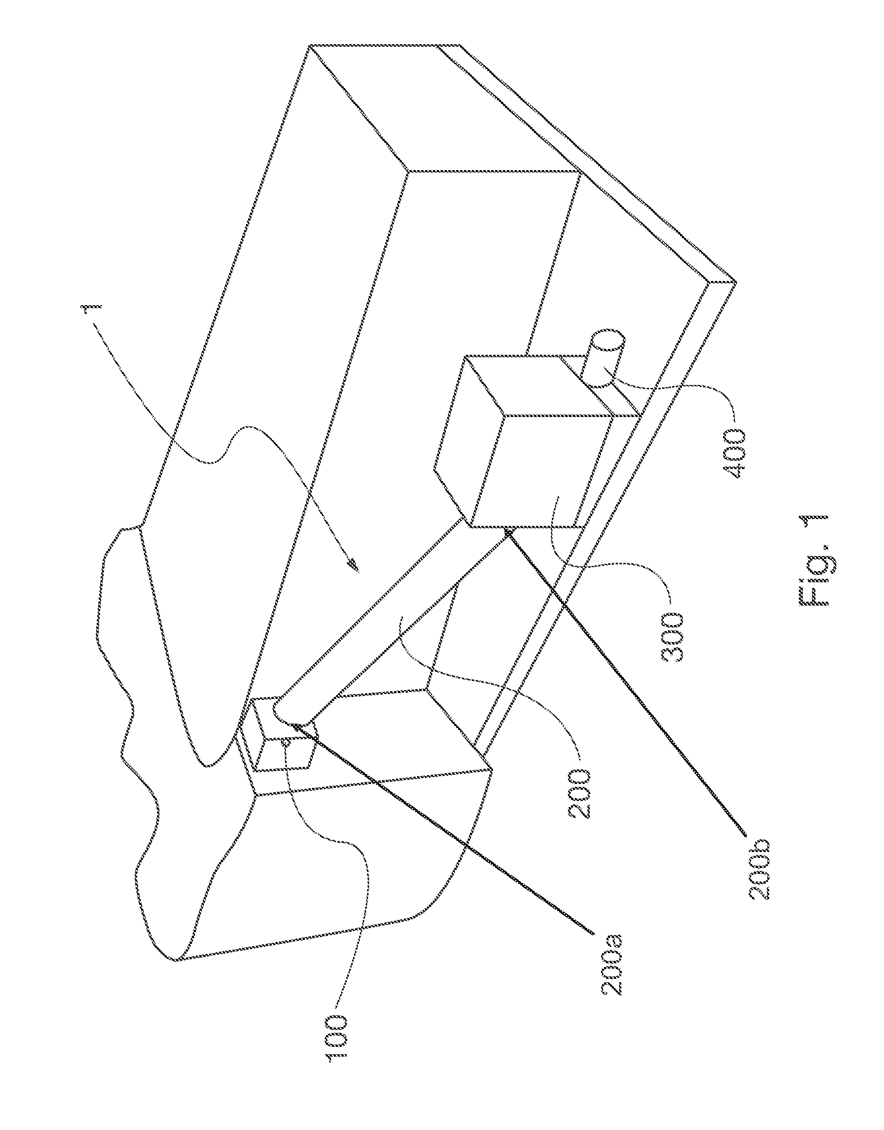
[0030]With reference to FIG. 1, the underwater unit 1 of the hydroelectric power plant according to the invention is designed for being positioned in a water basin of any kind, either natural (sea, lake, and so on) or artificial. Said underwater unit 1 generally comprises:[0031]an inlet port 100 for the water which is used for the production of the electric power, said inlet port 100 being substantially provided at the surface of the water basin;[0032]an outlet port 400 for allowing the water used for the production of the electric power to return to the water basin, said outlet port 400 being provided in depth in said water basin;[0033]a piping arrangement which connects said inlet port with said outlet port, said piping arrangement including a penstock 200 which comprises an inlet section 200a and an outlet section 200b, the outlet section 200b of said penstock being at a depth greater than 100 m and preferably equal to 150-300 m with respect to said inlet section 200a of said pen...


PUM


Abstract

The present invention refers to a underwater unit (1) for a hydroelectric power plant and a modular hydroelectric power plant (2) comprising a plurality of such units. The unit (1) according to the invention uses the principle of functioning of the traditional hydroelectric power plants and comprises a penstock (200) which involves a “head” of at least 100 m, and preferably of about 150-300 m, and carries elevated kinetic energy water masses from the surface of a water basin down to one or more turbines (301a-301f) provided in depth under the surface of the basin itself, so as to transfer the kinetic energy from the water to said turbines and to transform then the kinetic energy into electric power. Thanks to the use of variable volume discharge tanks (313a,313b) positioned downstream the turbines, it is possible to easily and effectively return the water masses used for the actuation of turbines themselves to the surrounding environment.

Description

TECHNICAL FIELD[0001]The present invention refers to a unit for a hydroelectric power plant. More in particular, the present invention refers to an underwater unit for a hydroelectric power plant.[0002]The present invention refers also to an underwater hydroelectric power plant comprising at least one such unit.PRIOR ART[0003]Hydroelectric power plants are widely spread and used for the production of electric power.[0004]These plants use flowing water masses for the production of electric power: water is conveyed into one or more turbines which rotate thanks to the thrust of the water; each turbine is coupled to an alternator which transforms the rotational movement into electric power. The speed given by the water to the turbines is generated through a height difference of at least 100 m and preferably of about 150-300 m, called “head”, which is converted into hydrodynamic pressure at the height at which the turbines are positioned.[0005]In order to have a reserve of water sufficie...

Claims


Application Information

Patent Timeline
IPC IPC(8): F03B13/10F03G7/04
CPCF03B13/10F05B2240/97Y02E60/17Y02E10/22F05B2250/02Y02E10/20Y02E60/16
Inventor DEANDREA, LUCAPORRARO, MARINABAEWERT, MASSIMO
Owner DEANDREA LUCA
Why Eureka
Try Eureka