
Commissioning Coded Light Sources

a light source and code technology, applied in the direction of electromagnetic transmission, close-range type systems, transmission, etc., can solve the problems of difficult to successfully extract the identifier of the control device, the sensitivity of the control device is a practical problem, and the response of the resulting control system is fast, so as to improve the commissioning effect of the light sour

Active Publication Date: 2012-08-09
KONINKLIJKE PHILIPS ELECTRONICS NV
View PDF2 Cites 42 Cited by
  • Summary
  • Abstract
  • Description
  • Claims
  • Application Information

AI Technical Summary

Benefits of technology

[0006]It is an object of the present invention to overcome this problem, and to provide means for improved commissioning of light sources. It is a particular objective to provide means for commissioning of light sources where coded light as received by a light detector comprises identifiers associated with a plurality of light intensities.
[0009]Advantageously, the inventive auto-commissioning method allows the commissioning process to be performed in a limited time period, avoiding the many collisions of signals present in the prior art. The method allows commissioning the light sources of luminaires located closest to the remote control device (i.e. those giving the strongest signal) first, before turning to the others. In other words, when the light emission of the identified light source is at least partly switched off its light contribution is reduced, thereby reducing the risk of collision with identifiers of other light sources. On average, the light sources close by will be first identified.
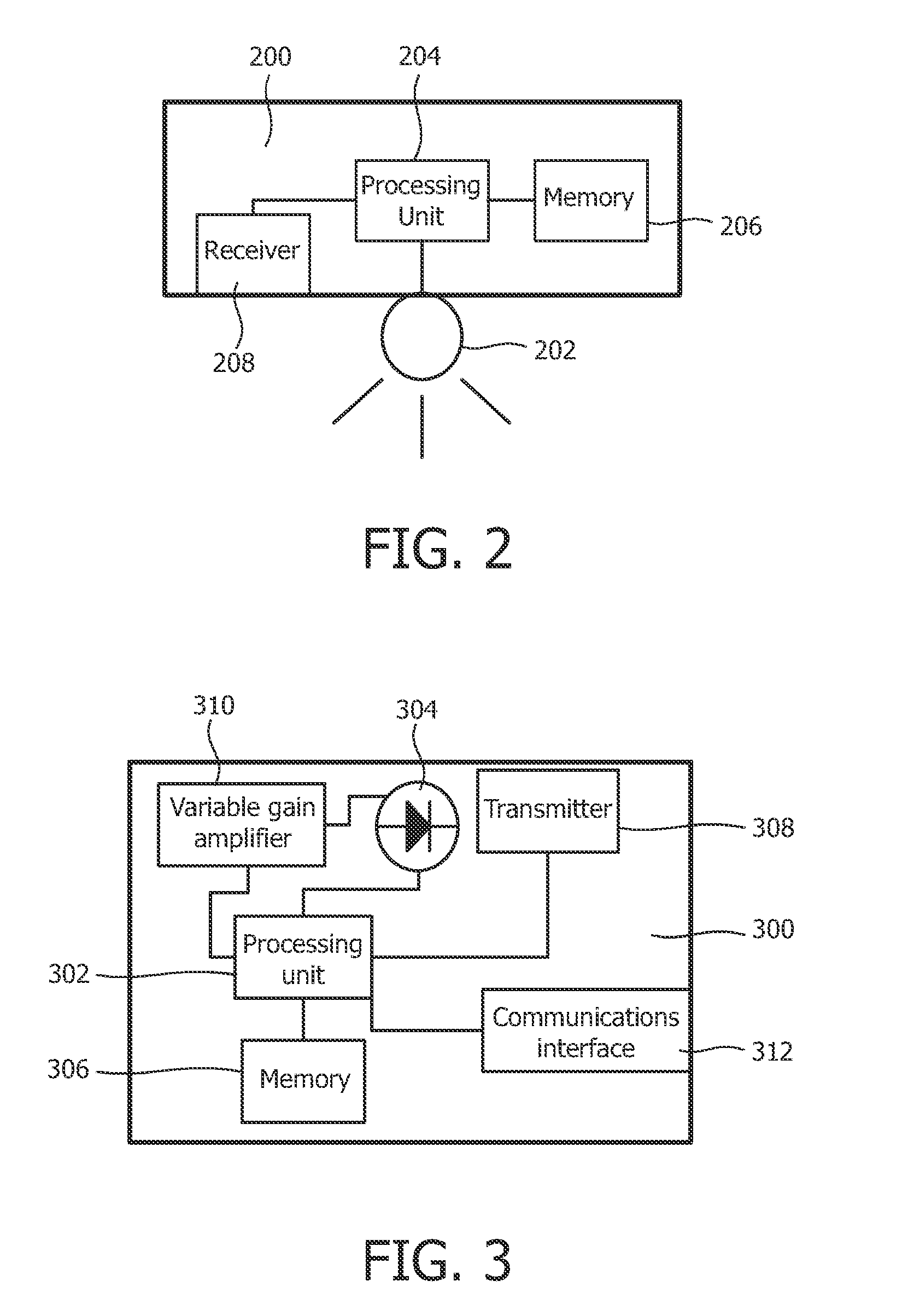
[0011]The remote controller may further comprise a variable gain amplifier coupled to the light detector and arranged to increase a sensitivity of the light detector until at least one identifier is detectable in the received light. Advantageously the sensitivity can be increased if no light source identifiers are detectable. Thereby the chance of detecting a light source may increase.
[0012]Even though the already identified light sources have dimmed the light emission it may still interfere with light sources associated with weak intensities. The remote controller may therefore further comprise a memory coupled to the processing unit and arranged to store identifiers of the plurality of light sources; wherein the processing unit is arranged to, during determination of the identifier of the light source, compare the identifier of the light source with the stored identifiers of previously identified light sources; and wherein the memory is arranged to add the identifier of the identified light source to the memory in response to the identified light source having been identified. Advantageously the remote controller may thereby reduce the risk of identifying the same light source twice.
[0013]The remote controller may be arranged to successively increase the sensitivity of the light detector, thereby enabling the processing unit to successively identify light sources one by one; and wherein the memory is arranged to store the identifiers of the successively identified light sources one by one into the memory in response to the successively identified light source having been identified. Hence such a remote controller may enable effective and successive identification of light sources one by one in a coded lighting system.
[0016]The processing unit may comprise a communications interface coupled to the processing unit, whereby the remote controller is capable of communicating information pertaining to identification of light sources to and / or from at least a second remote controller. Advantageously this enables the remote controller to exchange information with at least a second remote controller. By utilizing this information the commissioning may be improved e.g. by improving the reliability of the identification.

Problems solved by technology

This in turn may result in a fast response of the resulting control system.
The sensitivity of the control device forms a practical problem, especially for the luminaires situated remote from the location of the control device.
These luminaires only provide a small contribution to the light received by the control device, making it difficult to successfully extract their identifiers.
Furthermore, if the individual luminaires emit their identification in a random access fashion (e.g. via the framed ALOHA protocol), many collisions may occur before an identification code is extracted correctly.

Method used


Image

  • Commissioning Coded Light Sources
  • Commissioning Coded Light Sources
  • Commissioning Coded Light Sources

Examples


Embodiment Construction

[0025]The below embodiments are provided by way of example so that this disclosure will be thorough and complete, and will fully convey the scope of the invention to those skilled in the art. Like numbers refer to like elements throughout.

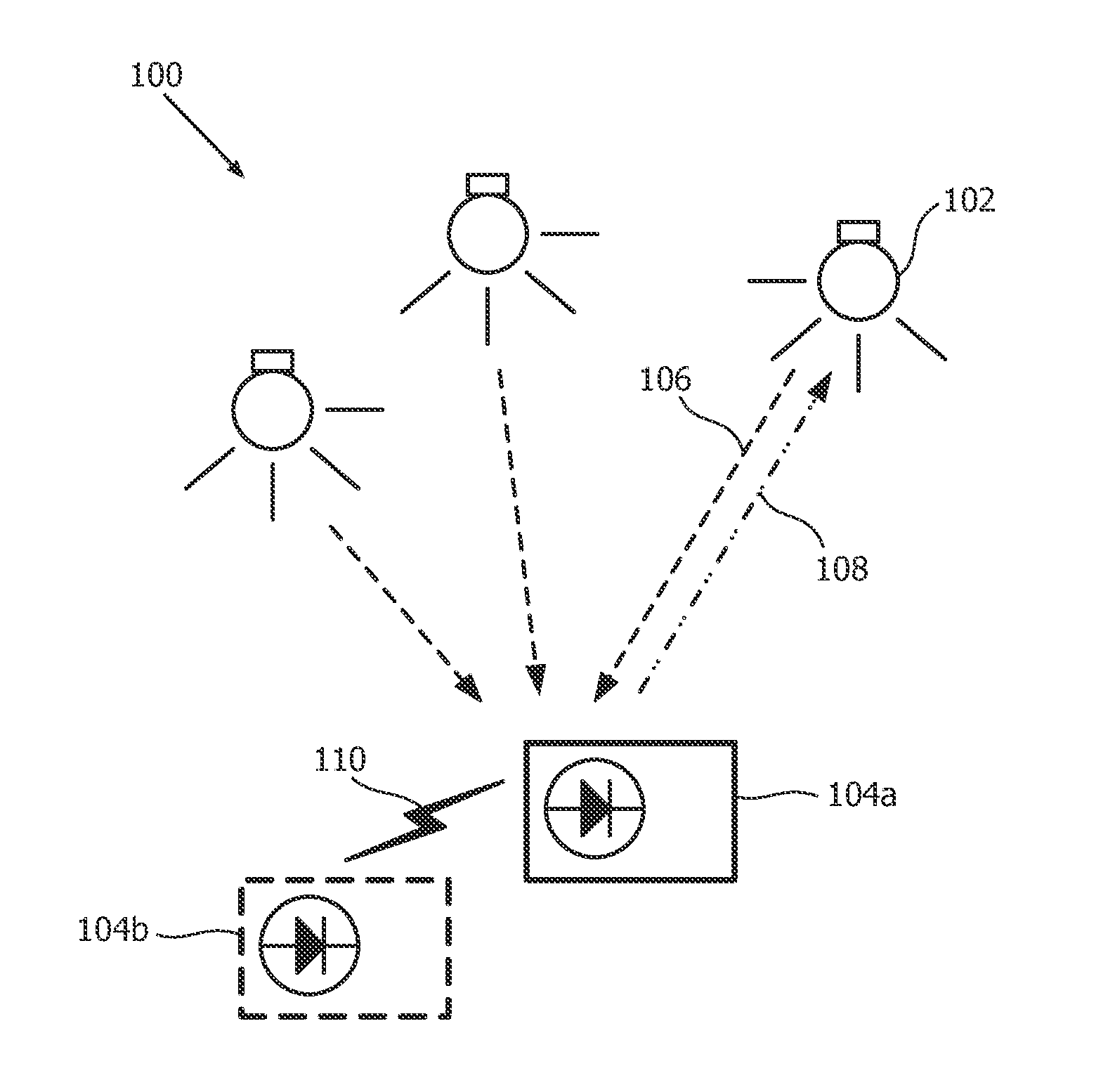
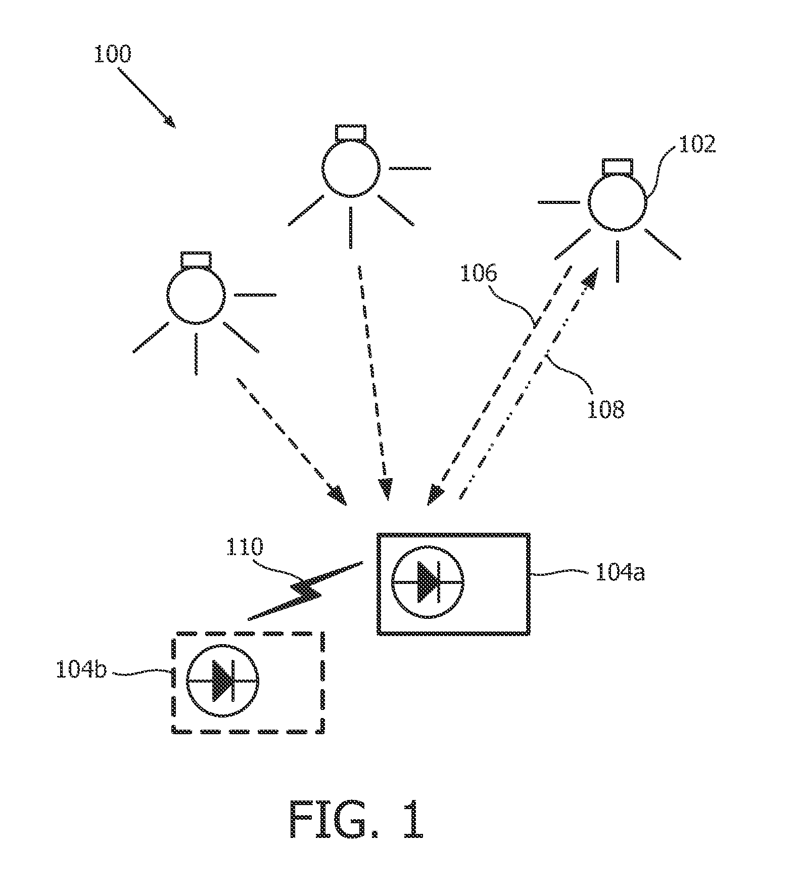
[0026]FIG. 1 illustrates a lighting system 100 comprising at least one light source, schematically denoted by the reference numeral 102. The light source 102 may be part of a lighting control system, thus the lighting system 100 may be denoted as a coded lighting system. It should be noted that the term “light source” means a device that is used for providing light in a room, for purpose of illuminating objects in the room. Examples of such light providing devices include lighting devices and luminaires. A room is in this context typically an apartment room or an office room, a gym hall, a car, a room in a public place or a part of an outdoor environment, such as a part of a street. Each light source 102 is capable of emitting light, as schematical...


PUM


Abstract

Commissioning a coded light source in a lighting system is accomplished by using a remote controller. When an identification of a light source is successful, a control message is sent to that light source to at least partly switch off its light emission. Thus the light contribution of the identified light source is suppressed. Thereby the chance of coded light from an already identified light source colliding with identifiers comprised in coded light emitted by other light sources is reduced. When no more coded light is detectable, a sensitivity of the remote controller can be increased until coded light again is detectable. Further light sources can then be identified and commissioned.

Description

FIELD OF THE INVENTION[0001]The present invention relates to commissioning a light source. Particularly it relates to methods and devices for commissioning a light source in a lighting system comprising a plurality of light sources capable of emitting coded light.BACKGROUND OF THE INVENTION[0002]The use of optical free space communications, i.e. visible light (VL) and infra-red (IR) communications, for the selection and advanced control of light sources has previously been proposed, and will be referred to as coded light (CL). For the transmission of CL, mostly, light emitting diodes (LEDs) are considered as light sources in the luminaires, which allow for a reasonable high modulation bandwidth. This in turn may result in a fast response of the resulting control system. Although LEDs are typically considered, other light sources (incandescent, halogen, fluorescent and high-intensity discharge (HID) lamps) also enable the embedding of identifiers in the light, generally, however, at ...

Claims


Application Information

Patent Timeline
IPC IPC(8): H05B37/02H04B10/114H04B10/116
CPCH04B10/1149H05B37/0272H04B10/116H05B47/19H05B47/199
Inventor KNIBBE, ENGEL JOHANNESFERI, LORENZOSCHENK, TIM CORNEEL WILHELMUS
Owner KONINKLIJKE PHILIPS ELECTRONICS NV
Learn More