Multiplier circuit
- Summary
- Abstract
- Description
- Claims
- Application Information
AI Technical Summary
Benefits of technology
Problems solved by technology
Method used
Image
Examples
first embodiment
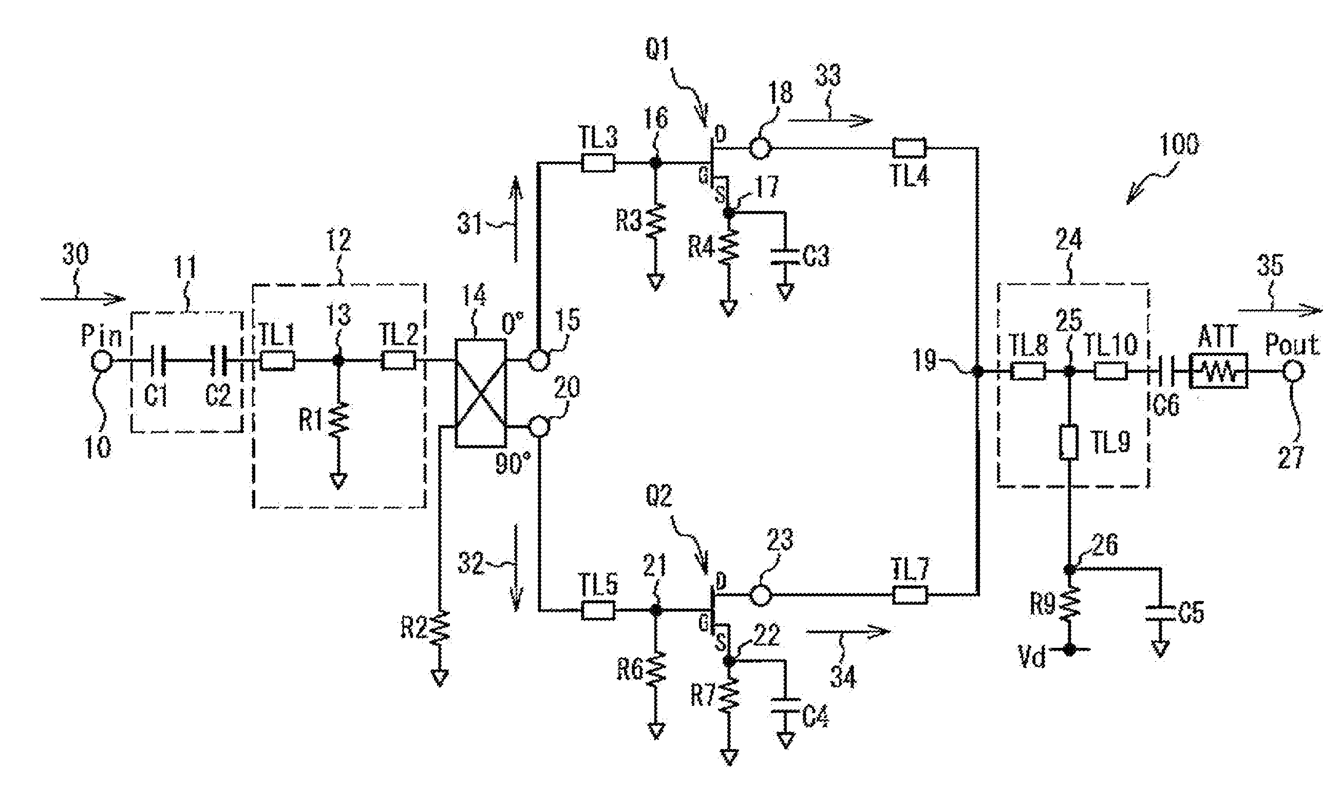
[0038]A description will be given of an example of a structure of a multiplier circuit in accordance with a first embodiment with reference to FIG. 3. FIG. 3 illustrates a circuit diagram of a multiplier circuit 200 in accordance with the first embodiment. The same components as those illustrated in FIG. 3 have the same reference numerals as FIG. 1. A description will be given of differences between the multiplier circuit 200 and the multiplier circuit 100. The other explanation is omitted.
[0039]The multiplier circuit 200 is different from the multiplier circuit 100 in a point that a combiner 28 is provided. The combiner 28 has the coupling point 19 to which the output of the first transistor Q1 and the output of the second transistor Q2 are coupled, the resistor R5 acting as a first resistor, and the resistor R8 acting as a second resistor. The combiner 28 is coupled to the drain terminal acting as the first output terminal of the first transistor Q1 and the drain terminal acting a...
second embodiment
[0047]A description will be given of an example of a structure of a multiplier circuit in accordance with a second embodiment with reference to FIG. 5. FIG. 5 illustrates a circuit diagram of a multiplier circuit 300 in accordance with the second embodiment. The same components as those illustrated in FIG. 5 have the same reference numerals as FIG. 1. A description will be given of differences between the multiplier circuit 300 and the multiplier circuit 200 of the first embodiment. The other explanation is omitted.
[0048]The multiplier circuit 300 is different from the multiplier circuit 200 of the first embodiment in a point that the distributed constant line TL6 is provided. The first terminal of the distributed constant line TL6 is coupled to the drain terminal acting as the second output terminal of the second transistor Q2 via the terminal 23. The second terminal of the distributed constant line TL6 is coupled to the first terminal of the resistor R8 acting as the second resist...
third embodiment
[0053]A description will be given of an example of a structure of a multiplier circuit in accordance with a third embodiment. FIG. 7 illustrates a circuit diagram of a multiplier circuit 400 in accordance with the third embodiment. The same components as those illustrated in FIG. 7 have the same reference numerals as FIG. 3. A description will be given of differences between the multiplier circuit 400 and the multiplier circuit 200 of the first embodiment. The other explanation is omitted.
[0054]The multiplier circuit 400 is different from the multiplier circuit 200 of the first embodiment in a point that a 90 degrees coupler 29 for a tripled wave acting as a combiner instead of the combiner 28. A resistor R13 coupled to the 90 degrees coupler 29 is a terminal resistor. As well as the combiner 28, the first output signal 33 and the second output signal 34 are input to the 90 degrees coupler 29. And, the 90 degrees coupler 29 restrains leakage of the first output signal 33 or the seco...
PUM
 Abstract
Description
Claims
Application Information
 - Generate Ideas
- Intellectual Property
- Life Sciences
- Materials
- Tech Scout
- Unparalleled Data Quality
- Higher Quality Content
- 60% Fewer Hallucinations
Browse by: Latest US Patents, China's latest patents, Technical Efficacy Thesaurus, Application Domain, Technology Topic, Popular Technical Reports.
© 2025 PatSnap. All rights reserved.Legal|Privacy policy|Modern Slavery Act Transparency Statement|Sitemap|About US| Contact US: help@patsnap.com


