Device management system

a technology of device management and management system, applied in the direction of digital output to print units, instruments, electrographic process apparatus, etc., can solve the problems of inability to appropriately manage power consumption amounts, and inability to obtain normal power consumption amounts, etc., to achieve the effect of managing power consumption amounts more appropriately

Inactive Publication Date: 2012-08-09
CANON KK
View PDF6 Cites 11 Cited by
  • Summary
  • Abstract
  • Description
  • Claims
  • Application Information

AI Technical Summary

Benefits of technology

[0006]An aspect of the present invention is to eliminate the above-mentioned problems with the conventional technology. The present invention provides a mechanism that allows to manage power consumption amounts more appropriately even when a device cannot normally obtain a power consumption amount.

Problems solved by technology

However, in the system described in Japanese Patent Laid-Open No. 2003-335026 or 2010-072870, when a power consumption measurement unit of a device that can measure a power consumption breaks down, information of power consumption amounts cannot be appropriately managed.
More specifically, power consumption amounts cannot be normally obtained until a repair of the power consumption measurement unit by means of component replacement or maintenance is completed.
Likewise, when the power consumption measurement unit is detachable, and is unexpectedly detached, power consumption amounts cannot be normally obtained.
They pose serious problems for the system which manages information of power consumption amounts in detail, and widely uses such information.

Method used


Image

  • Device management system
  • Device management system
  • Device management system

Examples


first embodiment

[0028]

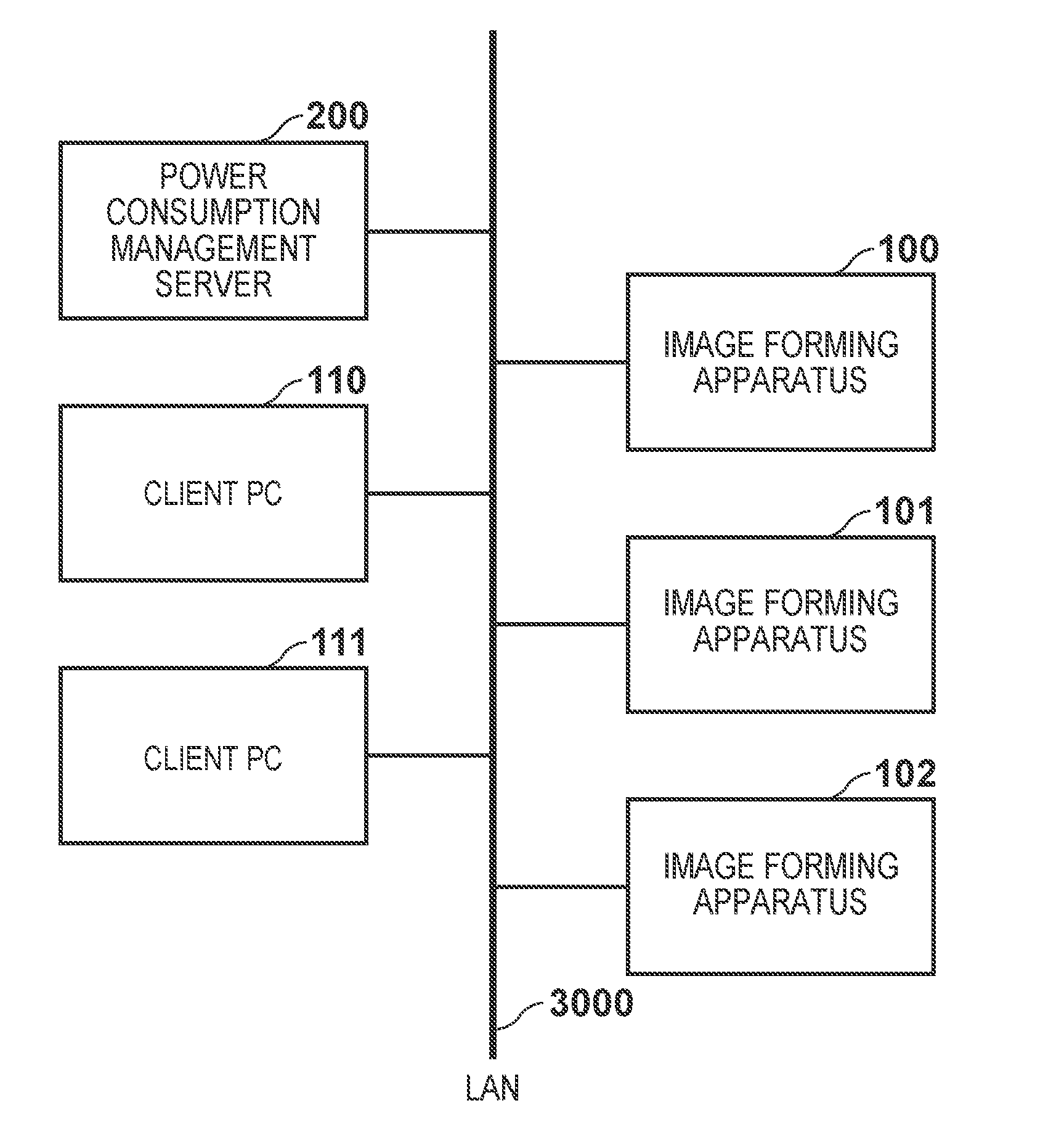
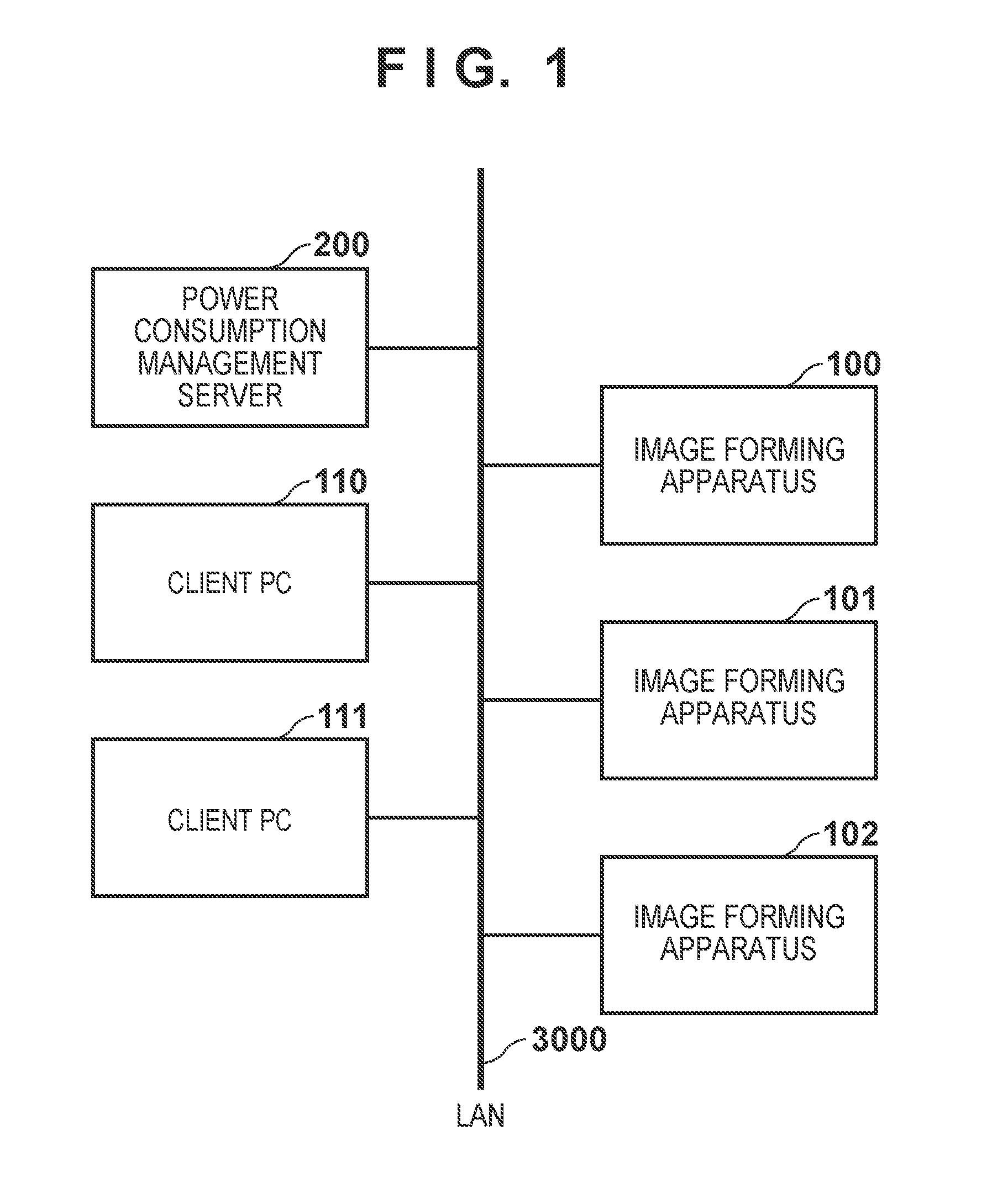
[0029]FIG. 1 shows the overall configuration of a device management system which mainly manages information associated with power consumptions of respective image forming apparatuses according to this embodiment. This system includes image forming apparatuses 100, 101, and 102 such as a printer, MFP, and FAX machine, client PCs 110 and 111 which can transmit print data to these image forming apparatuses, and a power consumption management server 200.

[0030]The power consumption management server 200 manages power consumption amounts in network devices such as these image forming apparatuses 100, 101, and 102. The client PCs 110 and 111, image forming apparatuses 100, 101, and 102, and power consumption management server 200 are connected via a LAN 3000 to be able to communicate with each other.

[0031]The power consumption management server 200 receives information which records operation logs (to be referred to as operation log information hereinafter) from each of the image for...

second embodiment

[0171]The second embodiment required to carry out the present invention will be described hereinafter. The second embodiment will exemplify a case in which the power consumption amount management program implemented by the power consumption management server 200 in the first embodiment is implemented in an image forming apparatus. By adopting such configuration, the same functions can be implemented by an image forming apparatus alone.

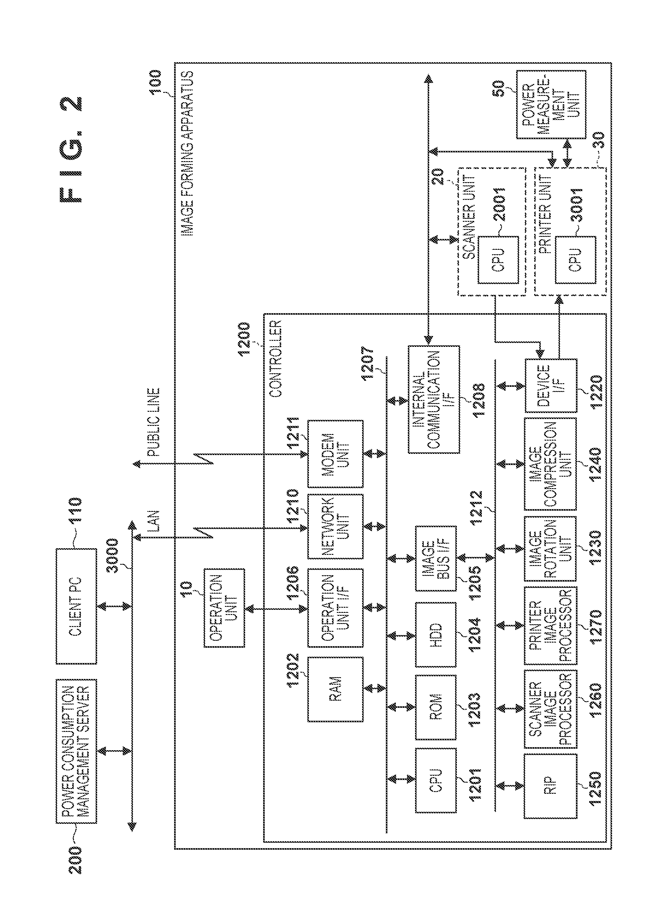
[0172]In order to implement the power consumption management function in the image forming apparatus, the power consumption amount management program shown in FIG. 10 is recorded and held in the HDD 1204 or RAM 1202 of the image forming apparatus, and is executed by the CPU 1201. The displayed contents shown in FIG. 12 and FIGS. 16A and 16B are displayed on a screen (the liquid crystal operation panel 11 shown in FIG. 4) of the operation unit 10 included in the image forming apparatus, or inputs are accepted on the screen of the operation unit 10.

[0173...


PUM


Abstract

Disclosed is a system in which a device which can measure a power consumption amount and a management apparatus which manages the device are connected to a network. In the device, a power consumption amount of the device is obtained by a power meter, and whether or not the power consumption amount of the device was normally measured is determined. The device notifies the management apparatus of information which associates at least the obtained power consumption amount with the determination result. In the management apparatus, the notification from the device is received, and the power consumption amount of the device is estimated and corrected with reference to the received determination result.

Description

BACKGROUND OF THE INVENTION[0001]1. Field of the Invention[0002]The present invention relates to a device management system which can calculate or measure a power consumption amount of a device.[0003]2. Description of the Related Art[0004]In recent years, in order to reduce emission amounts of greenhouse effect gases such as carbon dioxide, it has come to be required to reduce the amount of power consumed by the use of devices such as printers and MFPs. For this reason, it has come to be required to allow the user to recognize power consumption amounts (so-called“visualization”) when such devices are used. For example, Japanese Patent Laid-Open No. 2003-335026 discloses a technique in which, in a system configured by connecting a plurality of copying machines (image forming apparatuses) that can measure power consumptions, and a management apparatus for these copying machines to a network, the respective copying machines output data associated with measured power consumption amounts...

Claims


Application Information

Patent Timeline
Patent Type & Authority Applications(United States)
IPC IPC(8): G06F3/12
CPCG03G15/5004H04N1/00323H04N1/00344H04N2201/3205H04N1/00896H04N2201/0094H04N2201/3202H04N1/00832
Inventor IKARI, DAIKI
Owner CANON KK
Why Eureka
Try Eureka