Electrophoretic display sheet and manufacturing method therefor

a technology of display sheet and manufacturing method, which is applied in the direction of adhesives, optics, instruments, etc., can solve the problems of reducing display performance, reducing space, and difficult to obtain high sheet strength, and achieves the effects of high reliability, easy bending, and sufficient sheet strength

Active Publication Date: 2012-08-09
E INK CORPORATION
View PDF4 Cites 21 Cited by
  • Summary
  • Abstract
  • Description
  • Claims
  • Application Information

AI Technical Summary

Benefits of technology

[0036]In the electrophoretic display sheet according to the second aspect of the invention, it is preferable that the first substrate and / or the second substrate have flexibility.
[0037]Thus, the partitions and the binder layer are sufficiently affixed together, which enables the sheet strength to be sufficiently secured even in the case where the first substrate and / or the second substrate is thin and is easily bent. This allows the display performance of the electrophoretic display sheet to be maintained without a lift of the partitions and a leakage of the electrophoretic dispersion liquid across the partitions even when the external stress causes the first substrate and / or the second substrate to be bent or extend. An electrophoretic display sheet with high reliability is thus obtained. Further, in the case where both the first substrate and the second substrate have flexibility, the flexibility of the electrophoretic display sheet becomes very high.
[0038]Accordingly, it is possible to provide an electrophoretic display sheet having high reliability as well as having flexibility, and electronic paper that is lightweight and excellent in flexibility can be realized.

Problems solved by technology

The display performance is reduced because of a decrease in the space over which electrophoretic particles can migrate.
With the partition method of the electrophoretic display sheet disclosed in JP-A-2007-65288, however, there are problems in that a high sheet strength is hard to obtain, and it is difficult to secure sufficient display quality and reliability.
There are few portions where the two substrates opposite each other are in contact with each other, and therefore it is difficult to secure sufficient sheet strength.
Thus, it is difficult to secure intended display quality, resulting in poor reliability.

Method used


Image

  • Electrophoretic display sheet and manufacturing method therefor
  • Electrophoretic display sheet and manufacturing method therefor
  • Electrophoretic display sheet and manufacturing method therefor

Examples


first embodiment

1. Configuration of Electrophoretic Display Sheet

[0052]An electrophoretic display sheet according to the invention will first be described.

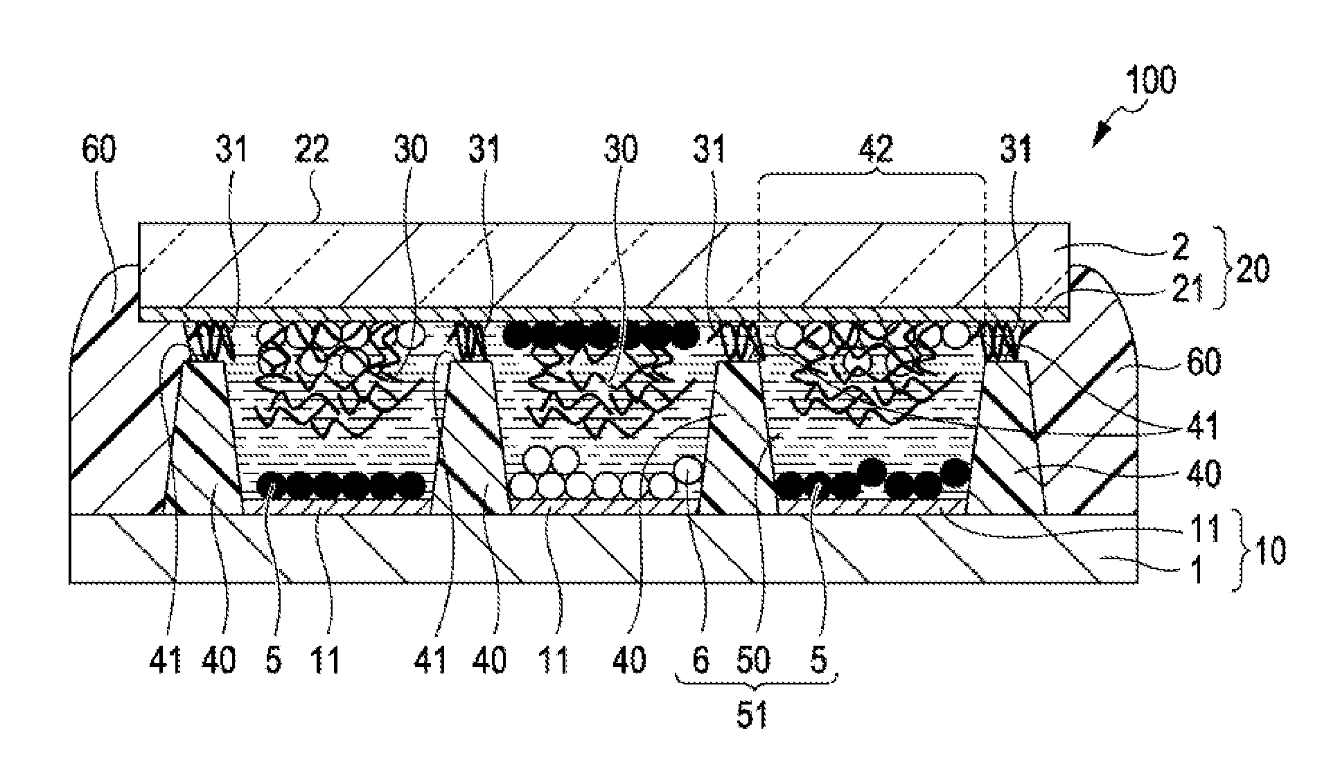
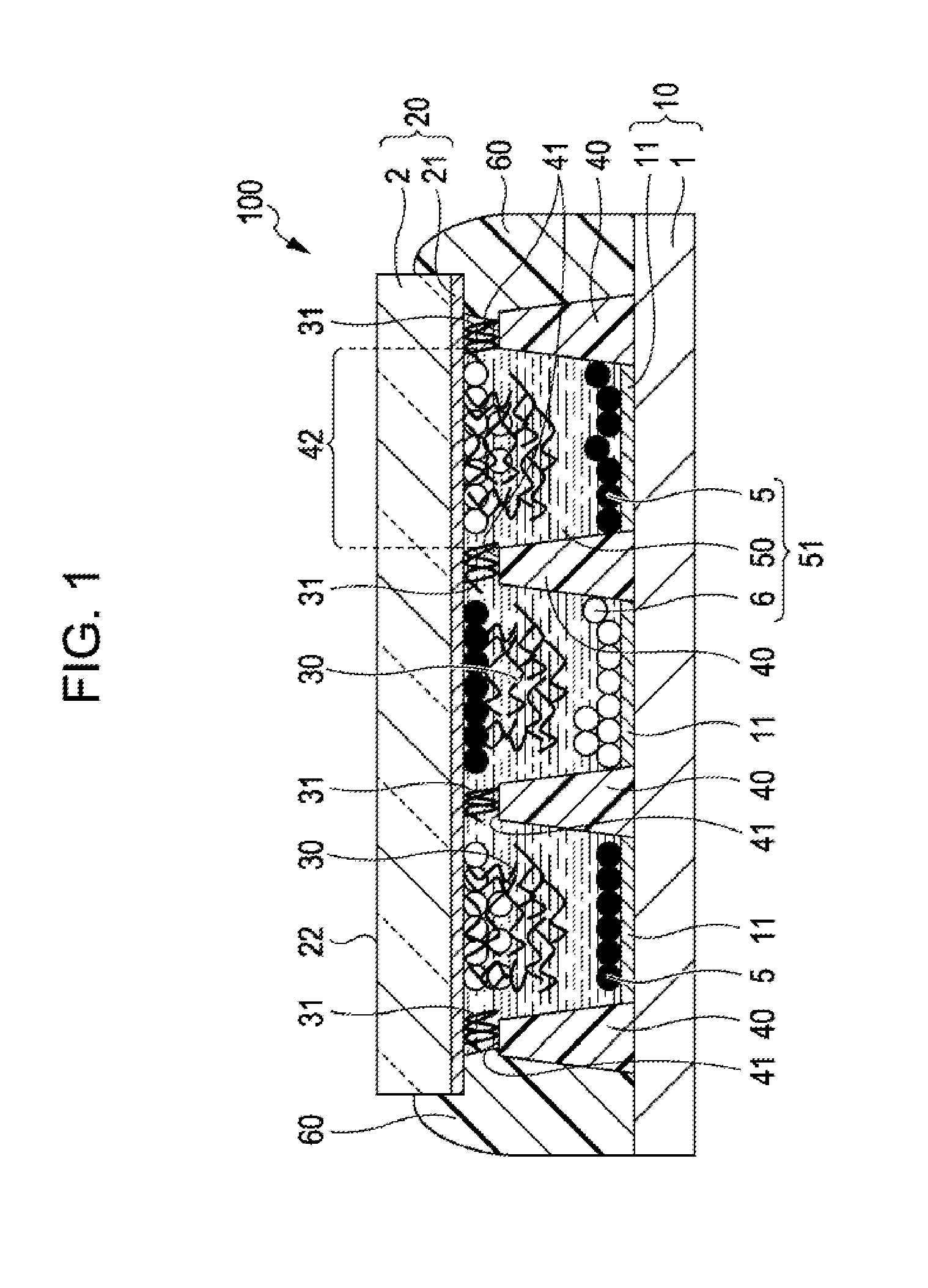
[0053]FIG. 1 is a sectional view of an electrophoretic display sheet according to a first embodiment. Note that, for the sake of convenience, in the description below, the upper and lower sides when the drawing in FIG. 1 is viewed from a front side are referred to as “upper” and “lower”, respectively.

[0054]An electrophoretic display sheet 100 illustrated in FIG. 1 displays a desirable image by making use of migration of electrophoretic particles. The electrophoretic display sheet 100 includes a second substrate (front plane) 20 serving as a display surface and a first substrate (back plane) 10 having a drive circuit and wiring.

[0055]The electrophoretic display sheet 100 includes the first substrate 10 and the second substrate 20, on one surface of which first electrodes 11 termed pixel electrodes and a second electrode 21 having optical transpare...

second embodiment

[0149]FIG. 5 is a sectional view of an electrophoretic display sheet according to a second embodiment, which corresponds to FIG. 1.

[0150]Hereinbelow, an electrophoretic display sheet 110 according to this embodiment will be described with reference to FIG. 5. Note that the same elements as in the first embodiment are denoted by the same numerals, and the same description is not repeated.

[0151]The electrophoretic display sheet 110 is the same as the electrophoretic display sheet 100 of the first embodiment, except that the binder layer 30 is formed of particles.

[0152]As illustrated in FIG. 5, in the electrophoretic display sheet 110, the resin of the binder layer 30 is not in a fibrous shape but in a particulate shape.

[0153]In such a manner, when colored white, the binder layer 30 in a particulate shape is more advantageous than that in a fibrous shape of the first embodiment. Because of the particulate shape, it becomes easy to increase the content of white pigments to be added and ...


PUM

PropertyMeasurementUnit
thicknessesaaaaaaaaaa

Abstract

An electrophoretic display sheet manufactured by forming on one surface of a first substrate partitions with an opening and applying and forming a binder layer on one surface of a second substrate, and then causing an electrophoretic dispersion liquid containing black particles and white particles dispersed in a dispersion medium to permeate into the binder layer and affixing the first substrate and the second substrate in a direction in which the surface of the binder layer with the electrophoretic dispersion liquid permeated therein and the surface of the partitions are opposite each other, and a method of manufacturing the electrophoretic display sheet are provided.

Description

BACKGROUND[0001]1. Technical Field[0002]The present invention relates to an electrophoretic display sheet and a manufacturing method therefor.[0003]2. Related Art[0004]Electrophoretic display sheets that utilize electrophoresis of particles are commonly used to form image display units of electronic paper, for example. The electrophoretic display sheets are excellent in terms of flexibility and power saving and are particularly suitable as image display units of electronic paper.[0005]An electrophoretic display sheet includes a pair of electrodes disposed opposite each other and a display layer disposed therebetween. The display layer is filled with a dispersion liquid in which, for example, white particles to be positively charged and black particles to be negatively charged are dispersed in a liquid phase dispersion medium. Such an electrophoretic display sheet is configured such that a voltage is applied between the pair of electrodes to cause the white particles and black partic...

Claims


Application Information

Patent Timeline
Patent Type & Authority Applications(United States)
IPC IPC(8): G02F1/167B29C65/02
CPCG02F1/167Y10T156/1002G02F2001/1672G02F1/1681
Inventor HAYASHI, KENJI
Owner E INK CORPORATION
Why Eureka
Try Eureka