High pressure smoke machine

a smoke machine and high-pressure technology, applied in the direction of steam generation using steam absorption, lighting and heating apparatus, applications, etc., can solve the problems of high corrosion of its vapor, lack of useful control abilities described previously, and use of pyrotechnic devices

Active Publication Date: 2012-08-09
REDLINE DETECTION
View PDF8 Cites 24 Cited by
  • Summary
  • Abstract
  • Description
  • Claims
  • Application Information

AI Technical Summary

Benefits of technology

[0023]The smoke generating device may further include a pressure regulator in fluid communication with the inlet conduit, wherein the pressure regulator is configured to control the pressure of the fluid delivered to the inner chamber.
[0024]The sm...

Problems solved by technology

The chemical compound titanium tetrachloride (TiCl4) produces a fine white vapor when exposed to moisture in the air; however, the material and its vapors are highly corrosive and it must be deployed carefully and in small quantities lest the corrosiveness cause damage.
Pyrotechnic devices are also used in such applications but lack the useful control abilities described previously.
The injection pressure of the vapor must be controlled in these applications as excessive pressure may damage the vapor generating device or the vessel or conduit into which the vapor is injected.
For instance, leaks in the fuel vapor recovery system (commonly known as the EVAP System) utilized with gasoline powered passenger vehicles are known to be a significant source of hydrocarbon pollution as the leak allows raw hydrocarbon evaporating from the fuel to escape to the surrounding atmosphere.
Such leaks upset the delicate ratio of fuel to air induced into the engine reducing the engine's performance and efficiency while increasing pollution causing emissions.
Some apparatus employed for this application can develop pressures as high as 2 PSI and are therefore not suitable for fuel vapor recovery system inspection.
The devices and apparatus developed for the inspection of fuel vapor recovery and vacuum induction systems are not always adequate for use in a high pressure forced induction system.
However, these connections will dislocate and leak when exposed to the higher...

Method used


Image

  • High pressure smoke machine
  • High pressure smoke machine

Examples


Embodiment Construction

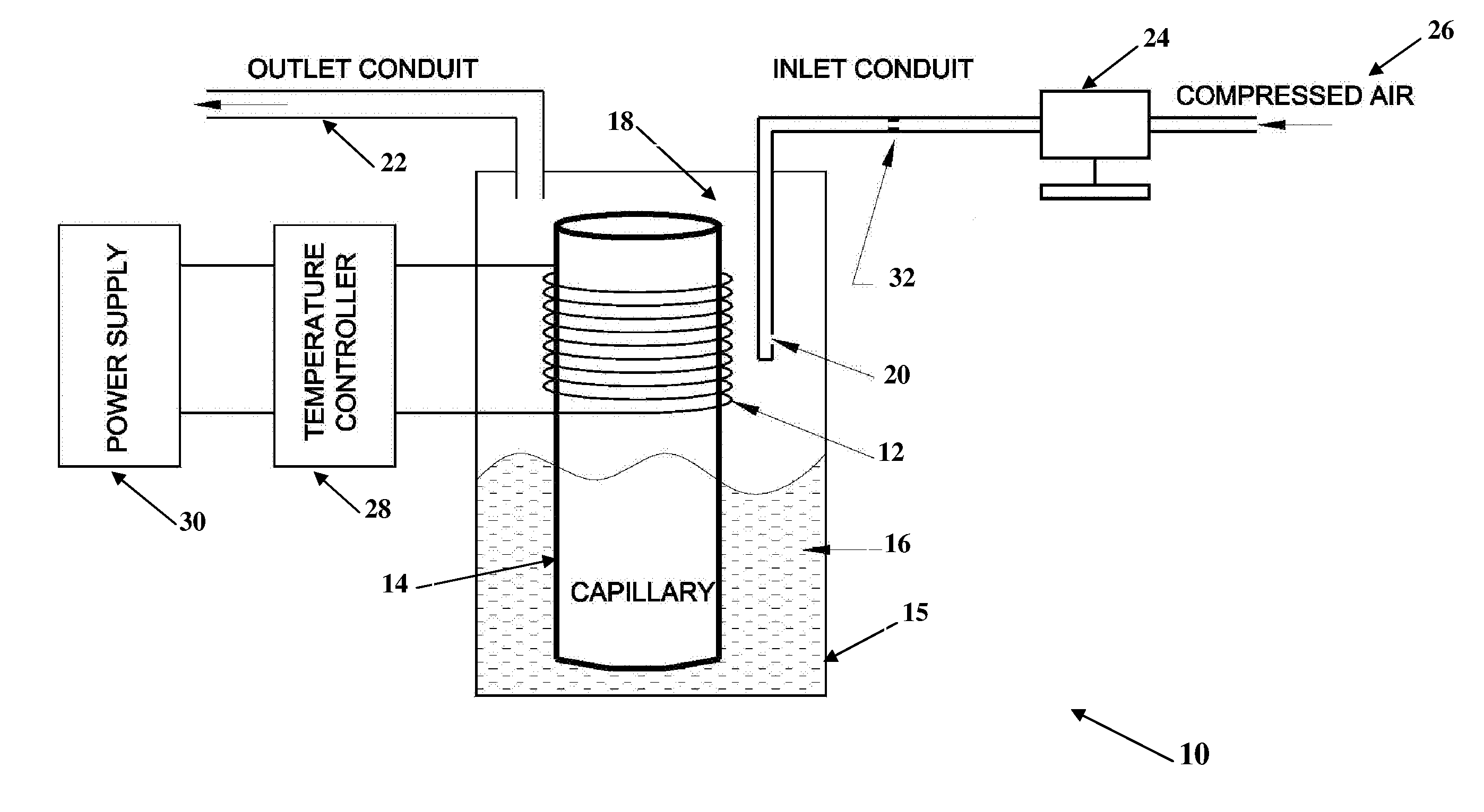
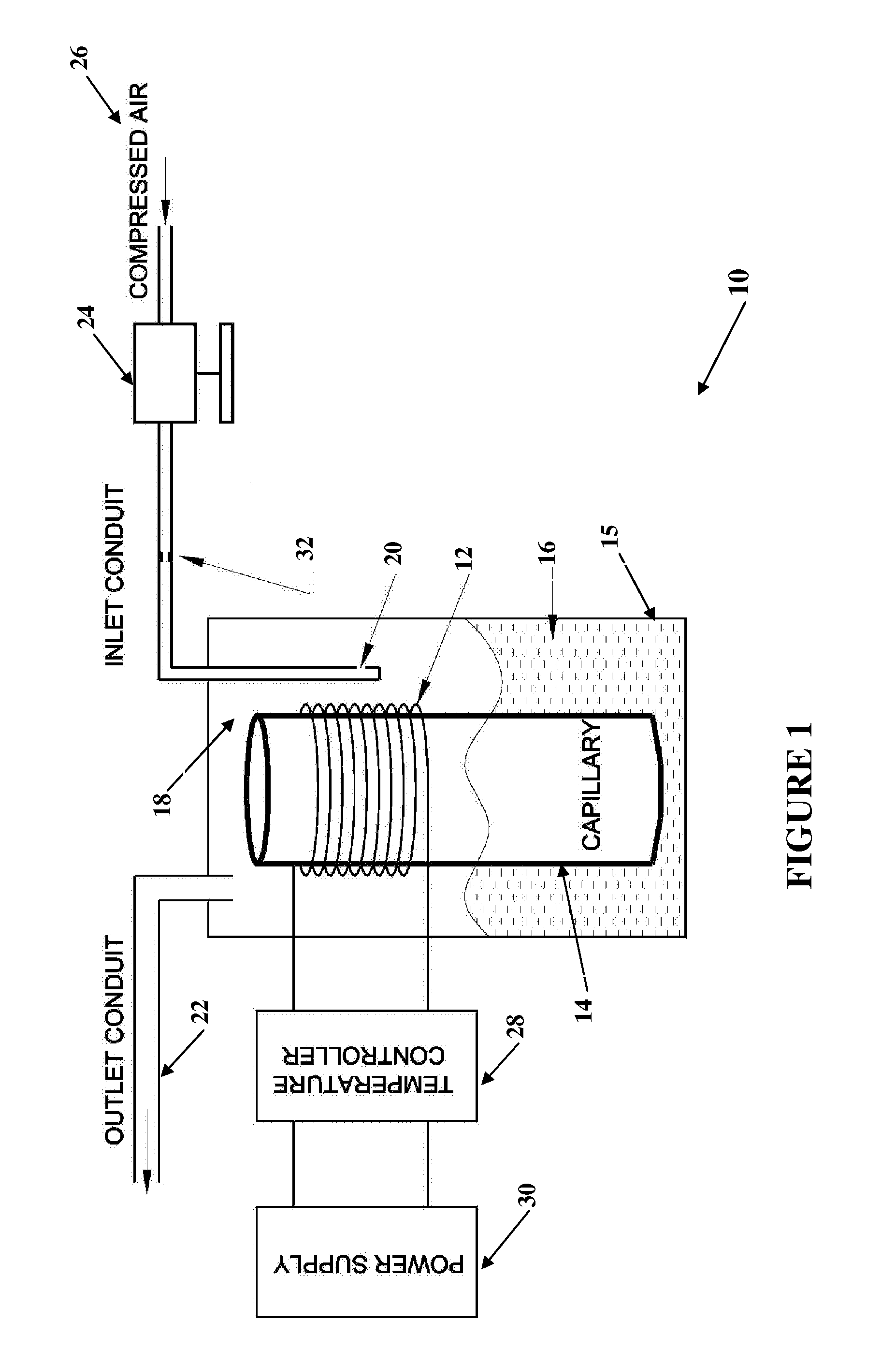
[0029]The current embodiment of the instant invention is configured for leak determination and location in internal combustion engines with forced induction systems up to 30 PSI. There are additional applications that will benefit from the ability to easily provide a pressurized vapor under controlled conditions to identify leaks. Similar embodiments will provide the capability to inspect applications such as; vehicle air break systems, engine combustion chambers, engine cooling systems, “super charged” engines (a higher pressure form of forced induction) and exhaust systems.

[0030]The required pressure and materials are established by the application in which the vapor is to be employed and as stated it is desirable to utilize compressed air as the propellant safely and reliably. To achieve this, the remaining variables of temperature and fuel to air ratio must be controlled to prevent dieseling. Of these temperature is the simplest to modify; however, simply reducing the temperatur...


PUM

PropertyMeasurementUnit
Temperatureaaaaaaaaaa
Surface areaaaaaaaaaaa

Abstract

There is provided a smoke generating device for use with a vaporizing material. The smoke generating device includes a housing defining an inner chamber configured to receive the vaporizing material, and a heating element disposed within the housing. A capillary is disposed within the inner chamber and is in thermal communication with the heating element. The capillary includes opposed first and second end portions, with the first end portion being disposable in the vaporizing material and the second end portion defining an opening in fluid communication with the internal chamber. The capillary is configured to convey the vaporizing material to the heating element. An inlet conduit in fluid communication with the inner chamber and fluidly connectable to a pressurized fluid source, and an outlet conduit in fluid communication with the inner chamber and configured to convey vapor from the inner chamber.

Description

CROSS-REFERENCE TO RELATED APPLICATIONS[0001]This application claims the benefit of U.S. Provisional Application No. 61 / 382,110, filed Sep. 13, 2010.STATEMENT RE: FEDERALLY SPONSORED RESEARCH / DEVELOPMENT[0002]Not ApplicableBACKGROUND[0003]1. Field of the Invention[0004]The present invention relates generally to a vapor generating device used while testing the fluid integrity of a fluid system, and more specifically to a vapor generating device that can safely produce a vapor at high pressures.[0005]2. Description of the Prior Art[0006]A visible vapor or smoke produced under controlled conditions which provide the ability to start and stop the vapor generation, to vary the flow of the vapor and to regulate the pressure of the vapor can be employed in many useful and beneficial ways. Such apparatus are well documented in the prior art and have been employed for various applications such as; air flow studies, theatrical effects, simulation of battlefield or structure fire conditions fo...

Claims


Application Information

Patent Timeline
IPC IPC(8): A61L9/03
CPCF41H9/06A63J5/025
Inventor STAUFFER, GENEPIERONI, KENNETH
Owner REDLINE DETECTION
Why Eureka
Try Eureka