Image heating apparatus

Active Publication Date: 2012-08-09
CANON KK
View PDF2 Cites 10 Cited by
  • Summary
  • Abstract
  • Description
  • Claims
  • Application Information

AI Technical Summary

Benefits of technology

[0008]A principal object of the present invention is to provide an image heating apparatus capable of avoiding level overheating of a heating belt member by enlarging a shift range of a recor

Problems solved by technology

However, in the image heating apparatus of the electromagnetic heating type and of the heating belt type, heat is concentrated at a portion having a very light weigh

Method used


Image

  • Image heating apparatus
  • Image heating apparatus
  • Image heating apparatus

Examples


embodiment 1

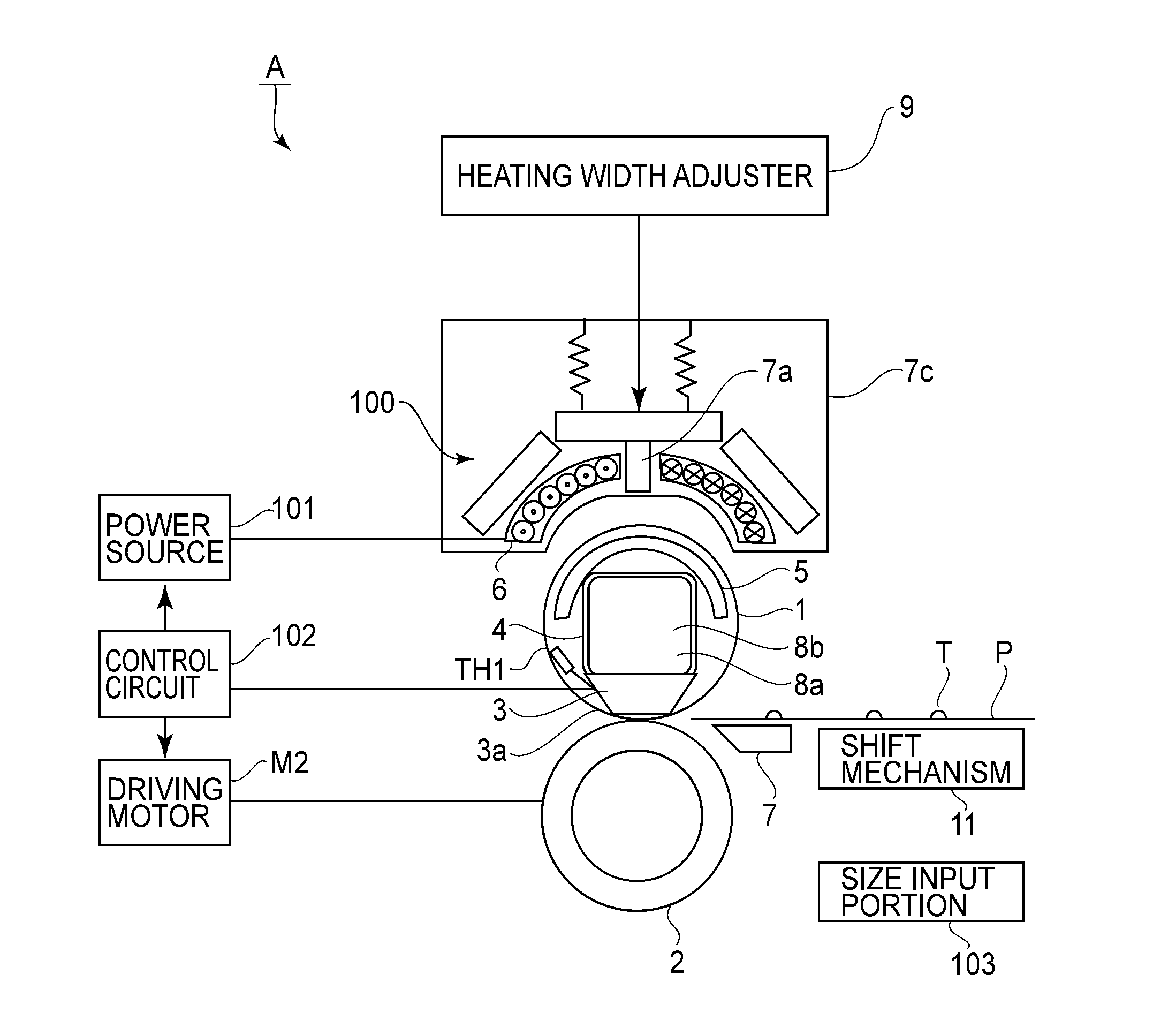
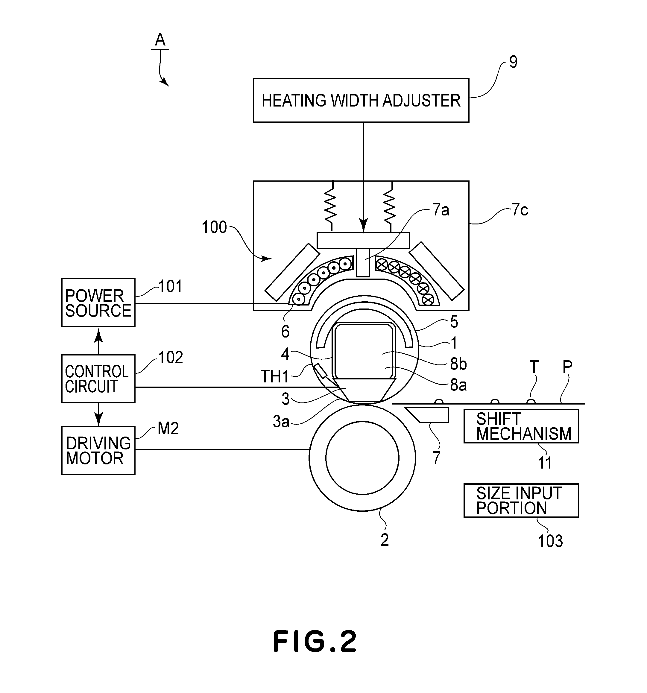
[0090]FIG. 8 is a flow chart of sheet passing control in Embodiment 1. As shown in FIG. 2, the recording material shift mechanism 11 which is an example of a reciprocating mechanism reciprocates a sheet passing position of the recording material P in the heating nip N in the widthwise direction, so that an sheet passing range of the recording material in the heating nip N is extendable.

[0091]The control circuit portion 102 which is a control means actuates the induction heating apparatus 100 to start the heating of the recording material with a heating width corresponding to the recording material size. Thereafter, the recording material shift mechanism 11 is controlled so that the sheet passing range of the recording material is extended depending on a cumulative member of heated sheets of the recording material.

[0092]The control circuit portion 102 stepwisely extends the sheet passing range of the recording material so that the sheet passing range follows enlargement of a temperat...

embodiment 2

[0107]FIG. 9 is an illustration of end portion temperature rise in the case where a recording material is not reciprocated. FIG. 10 is an illustration of timing of reciprocation of the recording material. FIG. 11 is an illustration of the end portion temperature rise at the time of sheet passing of 50th sheet in the case where the recording material is reciprocated. FIG. 12 is an illustration of the end portion temperature rise at the time of sheet passing of 100th sheet. FIG. 13 is an illustration of the end portion temperature rise at the time of sheet passing of 200th sheet. FIG. 14 is an illustration of the end portion temperature rise at the time of sheet passing of 500th sheet.

[0108]In this embodiment, a specific example of the constitution and control in Embodiment 1 will be described. In this embodiment, the peripheral speed of the fixing belt 1 is 300 mm / sec, and the full-color image is fixed on the A4-sized sheets (landscape feeding, longitudinal width=210 mm) at a rate of...

embodiment 3

[0124]Parts (a) and (b) of FIG. 15 are illustrations of a structure of a fixing device used in Embodiment 3. Part (a) of FIG. 15 is an enlarged cross-sectional side view of a principal portion of the fixing device as the image heating apparatus in this embodiment, and part (b) of FIG. 15 is a sectional view of a magnetic flux-shielding means 14.

[0125]As shown in (a) of FIG. 15, in this embodiment, the exciting coil 6 is provided inside the fixing belt 1, and a copper plate which is a magnetic flux-shielding plate is used for setting the heating width at a plurality of levels, depending on the recording material size, with respect to the heating belt 1. Incidentally, in this embodiment, constituent portions having the same functions as those in Embodiment 1 are represented by the same reference numerals or symbols and will be omitted from redundant description.

[0126]In a fixing device B, between the heating medium and the induction heating source, the magnetic-shielding means (14) fo...


PUM


Abstract

An image heating apparatus includes a rotatable image heating member for heating an image on a recording material, a magnetic flux generator for generating magnetic flux for heating the image heating member, an adjustor for adjusting the magnetic flux distribution so that the magnetic flux acting on an end portion region of the image heating member with respect to a rotational axis direction of the image heating member is decreased, a changing portion for changing a sheet passing position of the recording material with respect to the rotational axis direction within a set range, and a switching portion for switching, when the adjustor is actuated and sheets of the recording material are continuously passed, the set range from a range in which the sheet passing position does not overlap with the end portion region to a range in which the sheet passing position overlaps the end portion region.

Description

FIELD OF THE INVENTION AND RELATED ART[0001]The present invention relates to an image heating apparatus of a heating belt type in which a heating length of induction heating is variably constituted. Specifically, the present invention relates to control of a sheet passing reciprocate of a recording material when sheets of the recording material are continuously subjected to heating.[0002]An image forming apparatus in which a toner image is, after being transferred onto the recording material, heated and pressed in a heating nip of a fixing device of a roller heating type to be fixed on the recording material has been widely used. In the fixing device of the roller heating type, with the continuous heating of the sheets of the recording material, an overheating region is formed at roller end portions which are non-sheet passing regions. For this reason, control such that a relative positional relationship between the recording material conveyed into the heating nip and the heating ni...

Claims


Application Information

Patent Timeline
IPC IPC(8): G03G15/20
CPCG03G2215/00561G03G15/2042
Inventor TAKEUCHI, SUGURU
Owner CANON KK
Why Eureka
Try Eureka