Sandwich wedge clamp for fastening a solar panel

a solar panel and wedge clamping technology, applied in the field of systems, to achieve the effect of effective length of rivets, never being tampered with or adjusted, and careful manufacturing tolerances and quality control

Inactive Publication Date: 2012-08-09
DYNORAXX
View PDF5 Cites 34 Cited by
  • Summary
  • Abstract
  • Description
  • Claims
  • Application Information

AI Technical Summary

Benefits of technology

[0019]In another embodiment, the first pin and second pin are rivets. Rivets are advantageous because the effective length of the rivets can be set during manufacturing and can never be tampered with or adjusted. Thus, careful manufacturing tolerances and quality control can result in a product line where the clamp force is not too tight that the wedge plate cannot be moved into clamping position manually (i.e. without the use of a tool such as pliers, screwdrivers,

Problems solved by technology

However, because use of a single rail for different sizes of solar panels potentially creates less than optimal solar panel layout, the c

Method used


Image

  • Sandwich wedge clamp for fastening a solar panel
  • Sandwich wedge clamp for fastening a solar panel
  • Sandwich wedge clamp for fastening a solar panel

Examples


Embodiment Construction

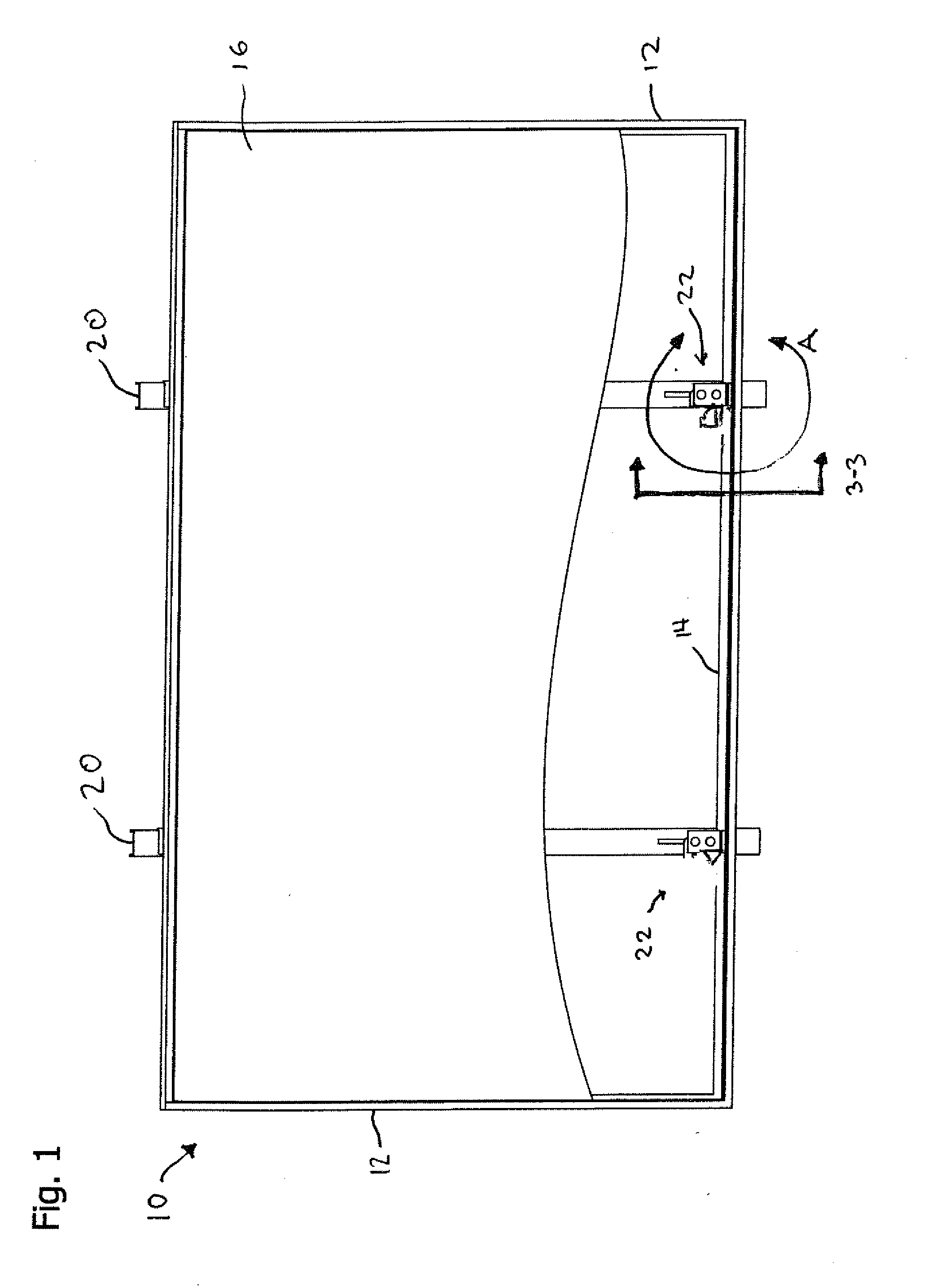
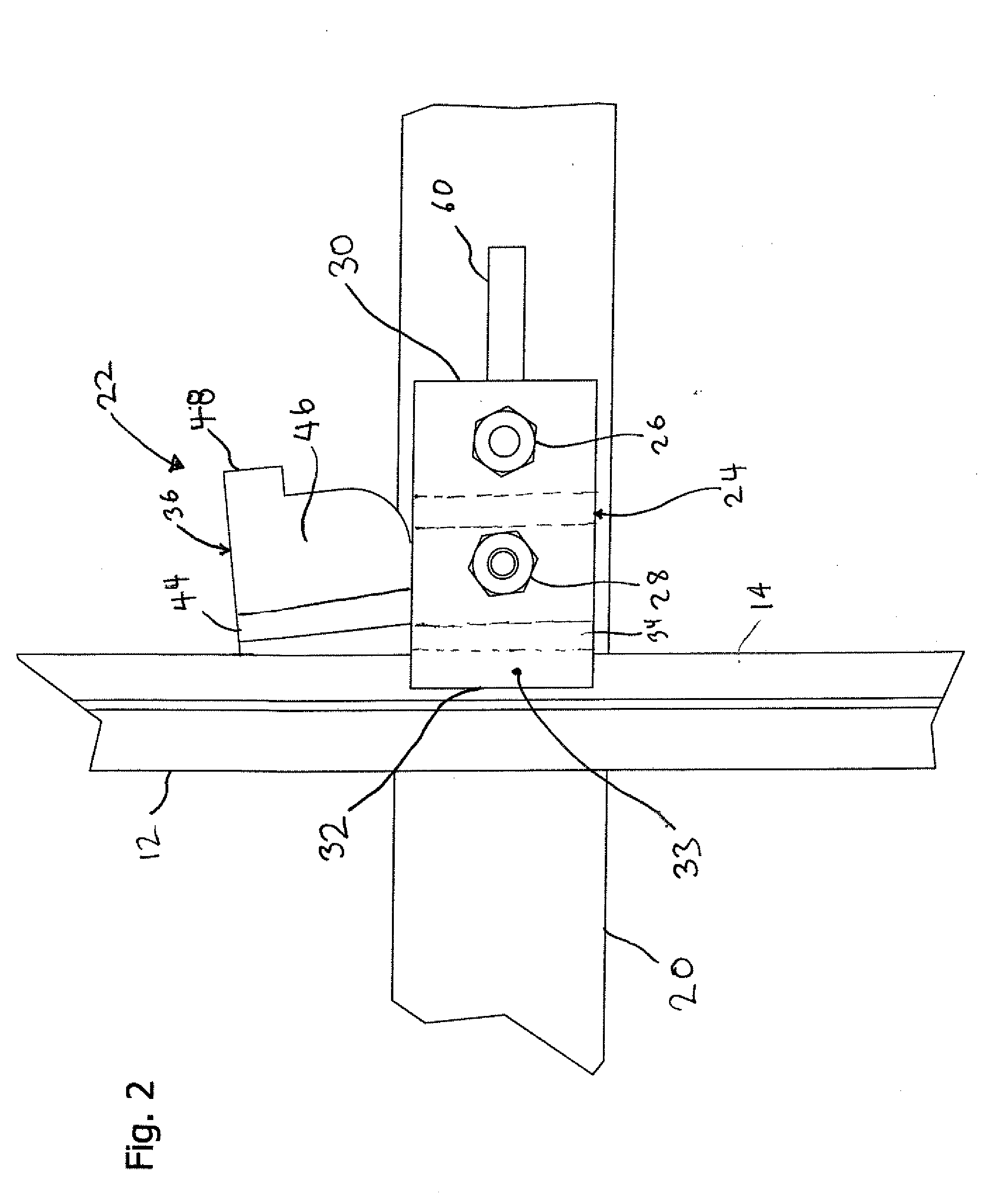
[0052]The present invention includes a mount mechanism for mounting a generally flat object to a supporting surface. In one embodiment, the generally flat object is a framed object. Preferably, the framed object is a solar panel. In one embodiment, the supporting surface is a rail—preferably elevated rail. With reference to FIG. 1, there is a solar panel 10 that has a frame 12 that surrounds the photovoltaic panel 16. The frame 12 has a flange 14 on the underside of the solar panel 10. The flange 14 is below the solar panel 10 so that is concealed from top view. The solar panel 10 is mounted on a pair of rails 20 or bars. The rails 20 are preferably elevated over the surface to which the solar panels are mounted. The rails 20 are typically attached to ballast boxes or trays or mounted on generally vertically extending posts that extend from ballast boxes or trays or are affixed directly to the underlying roof structure.

[0053]The present invention works best to secure a relatively fl...


PUM

PropertyMeasurementUnit
Thicknessaaaaaaaaaa
Lengthaaaaaaaaaa
Heightaaaaaaaaaa

Abstract

The present invention includes a solar panel mount. The solar panel mount comprises a mounting surface such as a base or a rail. The rail has a generally elongated clamp plate attached to the rail proximal to a first end and having a clamp pad proximal to a second end. There is a wedge plate pivotally connected to the rail proximal to a first end of the wedge plate. The wedge plate is attached between the rail and the generally elongated clamp plate. The wedge plate is pivotal from a disengaged position to a clamping position. The clamping position is the position of the wedge where the wedge head is between the clamp plate and the rail. In another embodiment, the mount is configured to support a solar panel having a flange that is clamped between the clamp pad and the rail.

Description

CROSS-REFERENCE TO RELATED APPLICATIONS[0001]This application claims the benefit of U.S. Provisional Application No. 61 / 462,898 filed Feb. 9, 2011, which application is incorporated by reference in its entirety herein.BACKGROUND OF THE INVENTION[0002]1. Field of Invention[0003]This invention relates generally to systems for mounting solar panels (such as photovoltaic cells) or other framed objects on a rail and more specifically to roof mounted racking systems for mounting framed photovoltaic cells.[0004]2. Discussion of Related Art[0005]Solar energy provides the opportunity to generate electricity without consumption of fossil fuels and is considered clean technology. In recent years, the development of technology for solar thermal systems and photovoltaic systems has improved the overall viability of solar energy. Thus, the demand for solar energy has increased.[0006]The cost of solar panel technology includes a significant investment in installation of the equipment. Thus, a tech...

Claims


Application Information

Patent Timeline
IPC IPC(8): F16B2/14B23P11/00
CPCF16B7/02F24J2/5254Y10T403/76Y10T29/49826Y02E10/47F24S2025/6008F24S25/632
Inventor RIZZO, NATHAN
Owner DYNORAXX
Why Eureka
Try Eureka