Detecting device, image forming apparatus, computer program product, and detecting system
a technology of image forming apparatus and detecting device, which is applied in the direction of pile separation, transportation and packaging, instruments, etc., can solve the problems of device abnormal operation and extremely difficult to identify which gear of the shaft is damaged in a unit connected by gears
- Summary
- Abstract
- Description
- Claims
- Application Information
AI Technical Summary
Benefits of technology
Problems solved by technology
Method used
Image
Examples
first embodiment
Modified Example of First Embodiment
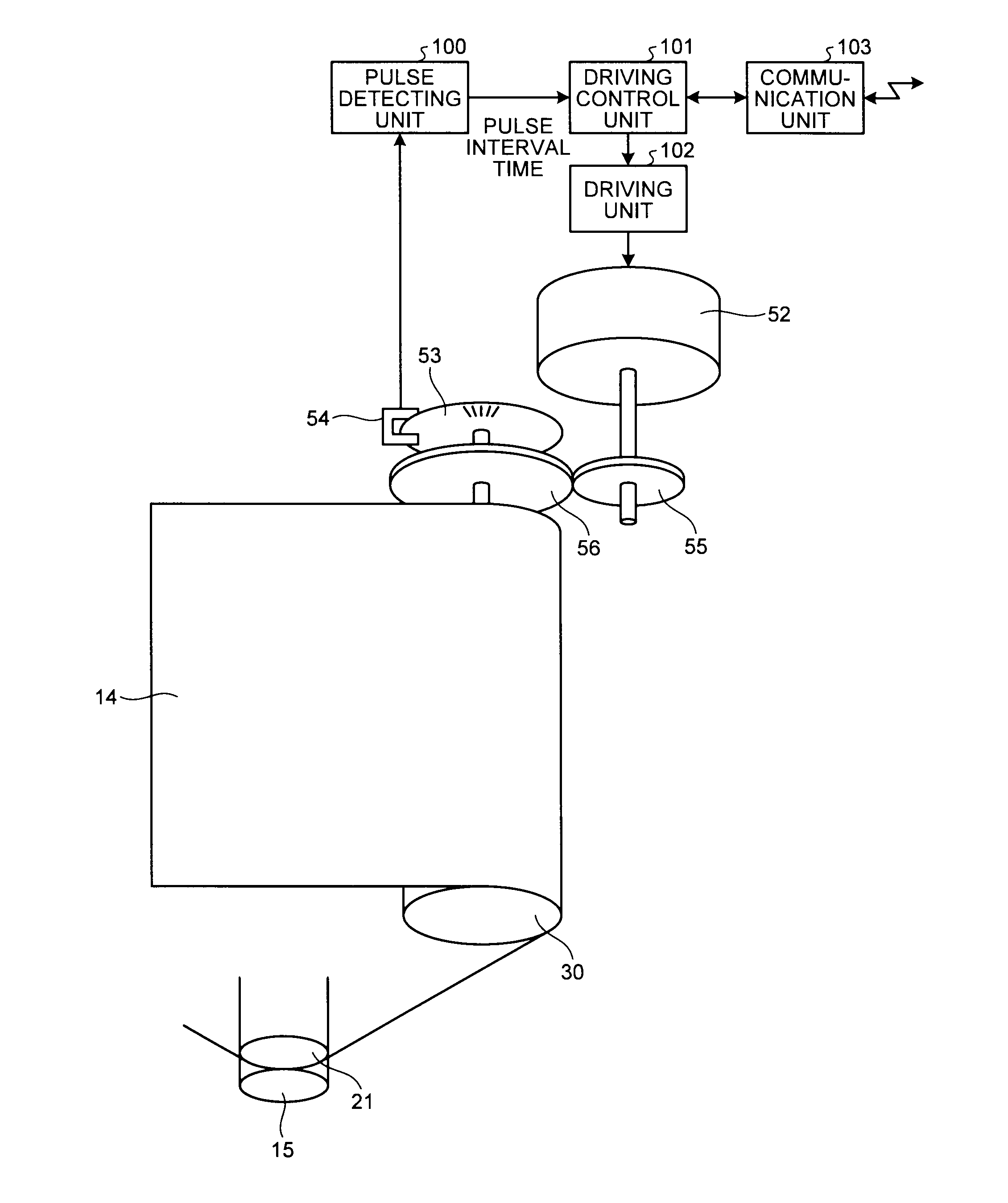
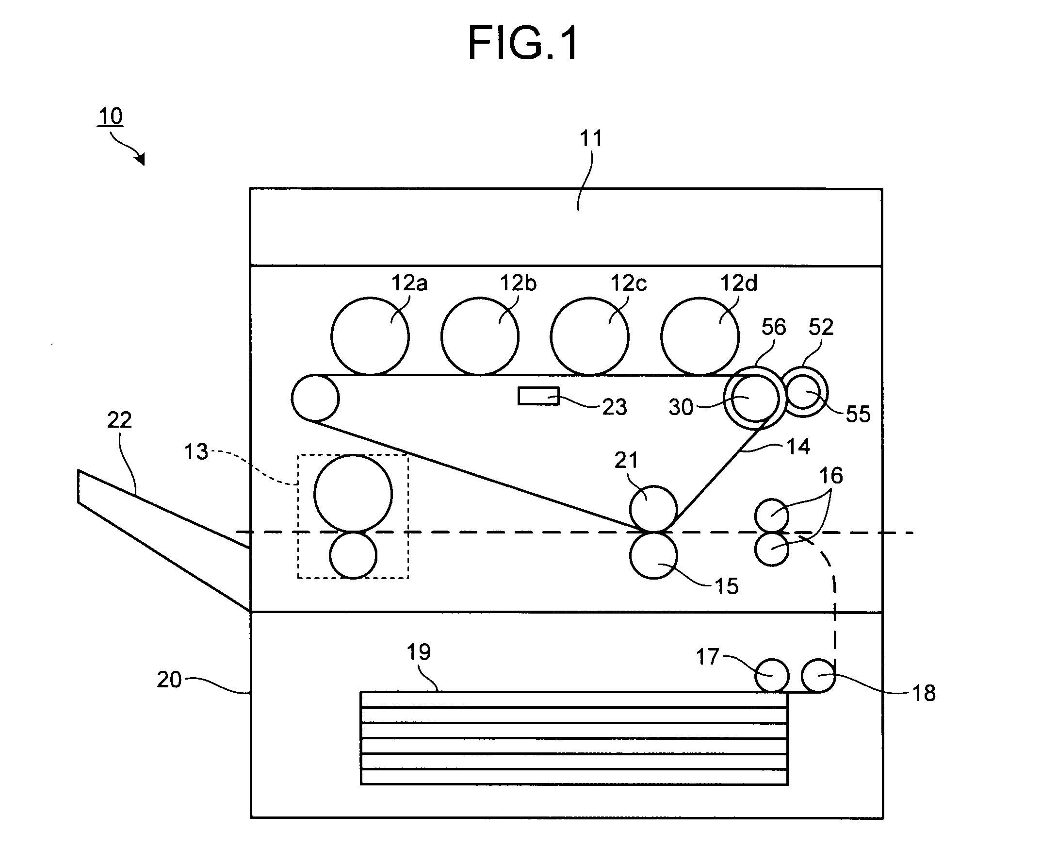
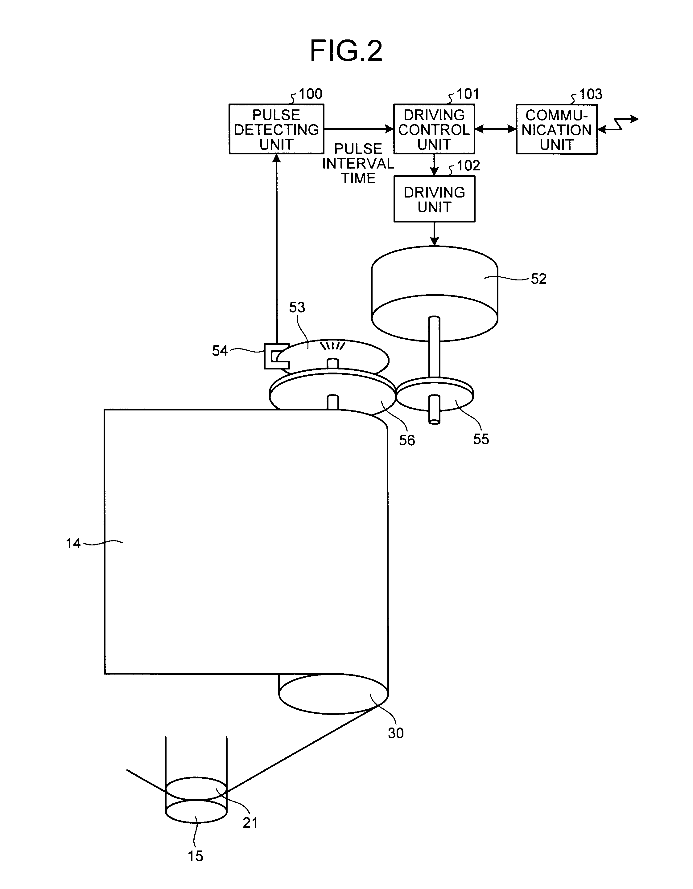
[0086]Next, an explanation is given of a modified example of the first embodiment. In the above explanation, gear damage detection and damaged-gear identifying are performed on the gears in the driving system that drives the intermediate transfer belt 14; however, it is not limited to this example. For example, the above-described first embodiment can be applied to the driving system that drives the photosensitive drums included in the photosensitive units 12a to 12d.
[0087]FIG. 12 illustrates an exemplary configuration of the driving system that drives a photosensitive drum. A gear 57 is attached to the rotation shaft of a motor 52′, and the motor 52′ is driven by a driving unit 102′ under the control of a driving control unit 101′. A gear 58, which connects to the gear 57, is attached to the rotation shaft of a photosensitive drum (rotary drum) 60, and the photosensitive drum 60 is driven by the motor 52′ via the gear 57 and the gear 58 while th...
second embodiment
[0093]Next, an explanation is given of a second embodiment. In the above-described first embodiment, if the connected gears include a damaged gear, the peak with the maximum peak value is detected with respect to the auto-correlation function for the measured rotating speed of the gear so that a damaged gear is identified. Conversely, according to the second embodiment, a ratio is obtained, which is the ratio between the value of the auto-correlation function corresponding to the rotation period, i.e., the delay time that is unique to each gear, which is obtained in advance in a state where each of the connected gears is a normal gear, and the value of the auto-correlation function, which is calculated by using the measured rotating speed with respect to one of the connected gears, corresponding to the delay time that is unique to each gear. Then, the value of the ratio obtained for each gear is compared with the threshold that is predetermined for each gear, and the gear whose rota...
third embodiment
[0113]Next, an explanation is given of a third embodiment. The third embodiment includes an example of presenting, to a user, damaged-gear information that is output from the damaged-gear detecting device according to the above-described first embodiment, the modified example of the first embodiment, and the second embodiment. FIG. 16 illustrates an exemplary hardware configuration of a multifunction peripheral that can be used in each of the embodiments and the modified example. The multifunction peripheral illustrated in FIG. 16 may include the configuration of the image forming apparatus 10, which has been explained with reference to FIG. 1.
[0114]As illustrated in FIG. 16, the multifunction peripheral has a configuration in which a controller 410 and an engine unit (Engine) 460 are connected to each other via a peripheral component interface (PCI) bus. The controller 410 is a controller that controls the overall multifunction peripheral and controls drawings, communication, and i...
PUM
 Abstract
Description
Claims
Application Information
 - R&D Engineer
- R&D Manager
- IP Professional
- Industry Leading Data Capabilities
- Powerful AI technology
- Patent DNA Extraction
Browse by: Latest US Patents, China's latest patents, Technical Efficacy Thesaurus, Application Domain, Technology Topic.
© 2024 PatSnap. All rights reserved.Legal|Privacy policy|Modern Slavery Act Transparency Statement|Sitemap


