Burnishing tool and method for burnishing

a technology of burnishing tools and tools, which is applied in the field of burnishing tools and, can solve the problems of the tool life, limiting the access to the workpiece, and limiting the speed of burnishing, so as to reduce the processing load, prevent or minimize plastic deformation and/or creep of the material, and increase the constraint on the bearing

Active Publication Date: 2012-08-16
SURFACE TECH HLDG
View PDF15 Cites 25 Cited by
  • Summary
  • Abstract
  • Description
  • Claims
  • Application Information

AI Technical Summary

Benefits of technology

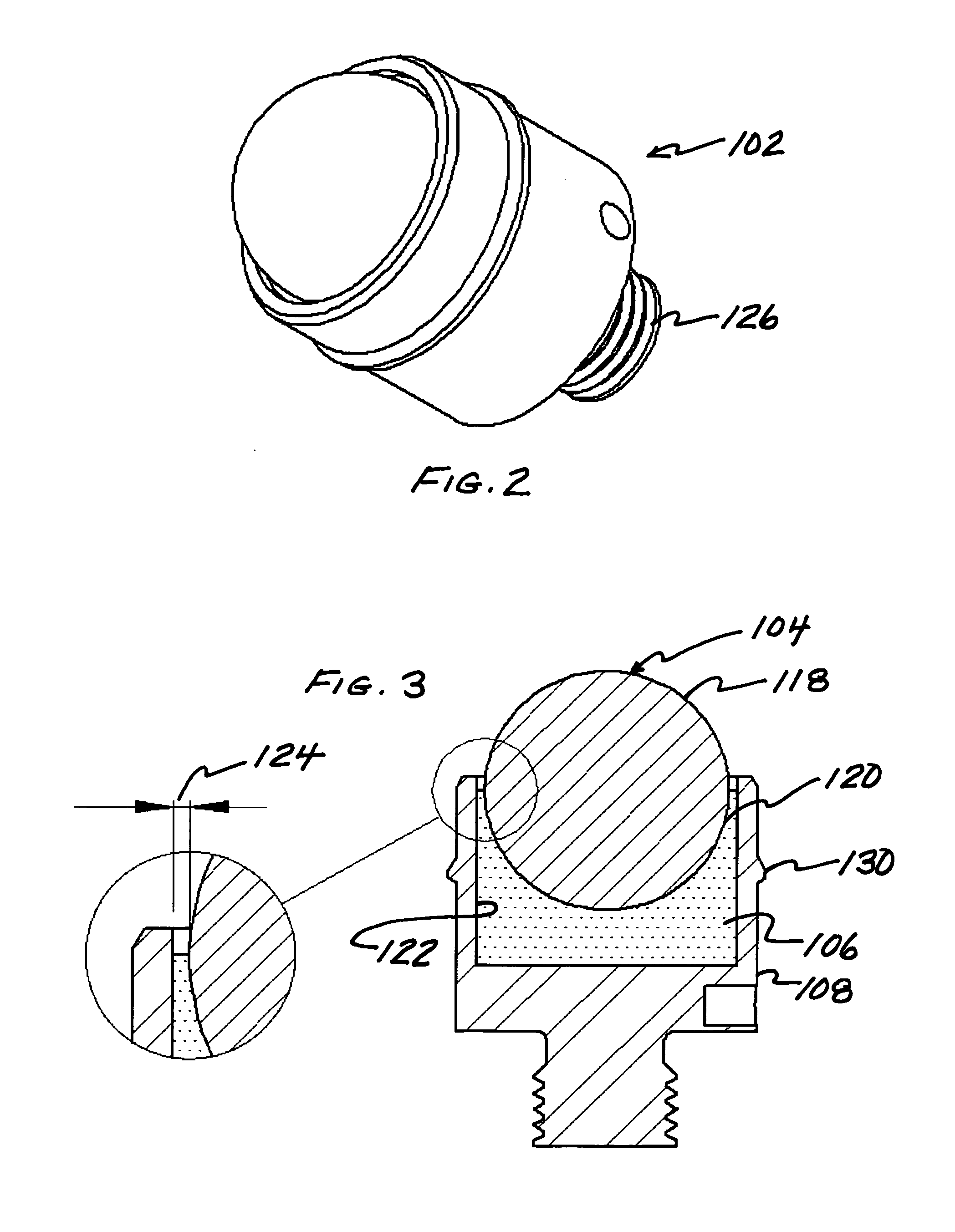
[0020]In a preferred embodiment of the invention, at least a portion of the bearing is supported by an encasement such that it prevents or minimizes plastic deformation and / or creep of the material forming the bearing when loads exceed the yield stress of the bearing material during use of the burnishing tool.

Problems solved by technology

Using a suitable high-hardness rolling element and the appropriate force for the work piece material, elimination of the tooling marks can leave a near mirror finish limited only by the finish of the rolling element.
Unfortunately, such tools are bulky, limiting access to the work piece, suffer from continual wear, and develop heat in operation that can limit the speed of burnishing and the tool life.
Unfortunately, such burnishing tools must be continuously connected to systems providing a source of the pressurized fluid for supporting and for extending the rolling element outwardly from the tool head.
Recovery of the hydrostatic fluid as it is expelled under pressure from the burnishing tool either limits the tool to closed machine tool applications, or requires further complexity by requiring a means of fluid recovery.
Hydrostatic bearing tools also have a limited angular range over which the force can be applied to the rolling element.
This often results in excessive wear that limits the life of the rolling element.
Therefore, hydrostatic bearing tools must be maintained in an alignment nearly normal to the surface of the work piece during the burnishing operation, thereby limiting the range of potential applications.

Method used


Image

  • Burnishing tool and method for burnishing
  • Burnishing tool and method for burnishing
  • Burnishing tool and method for burnishing

Examples


Embodiment Construction

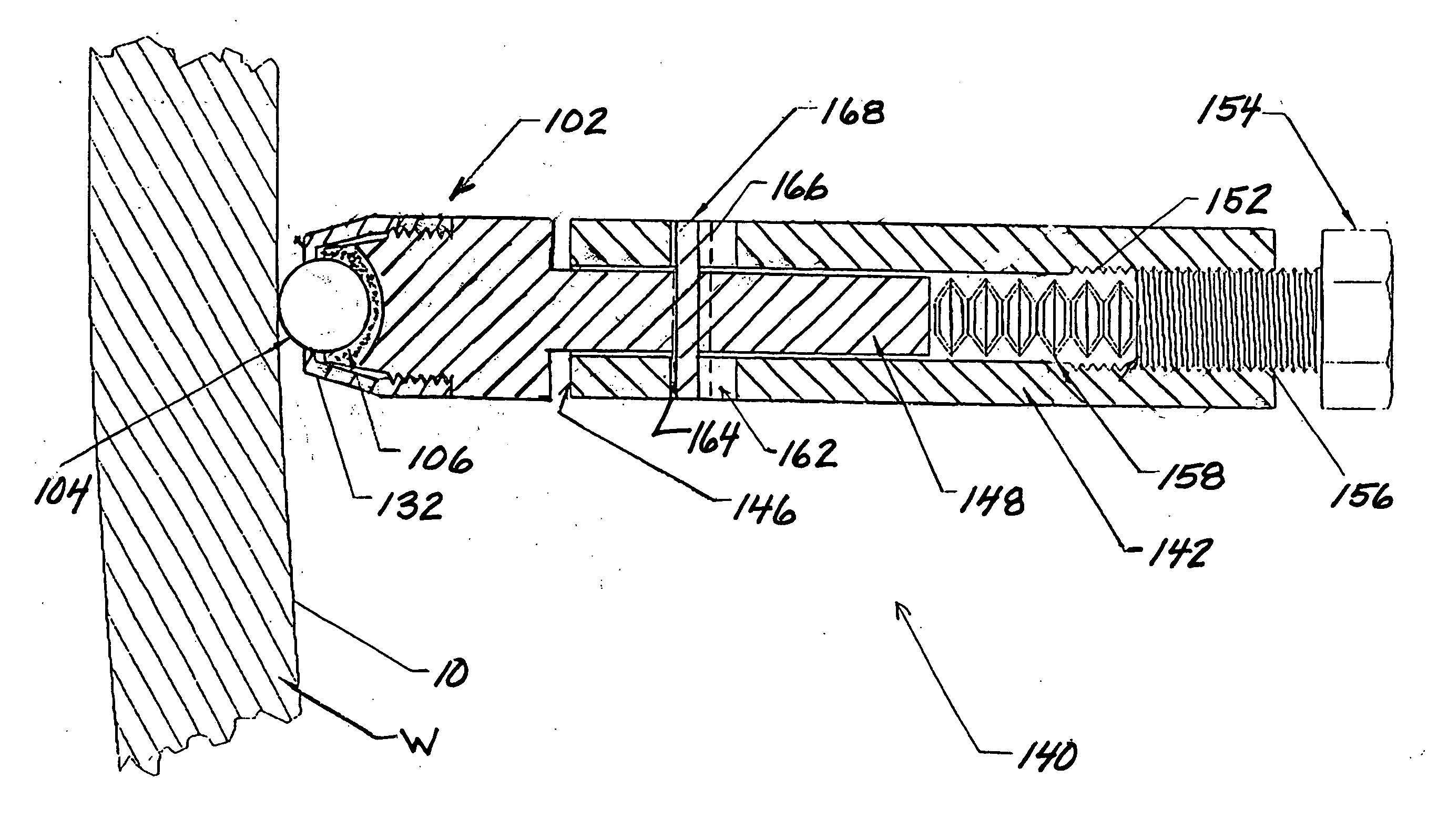
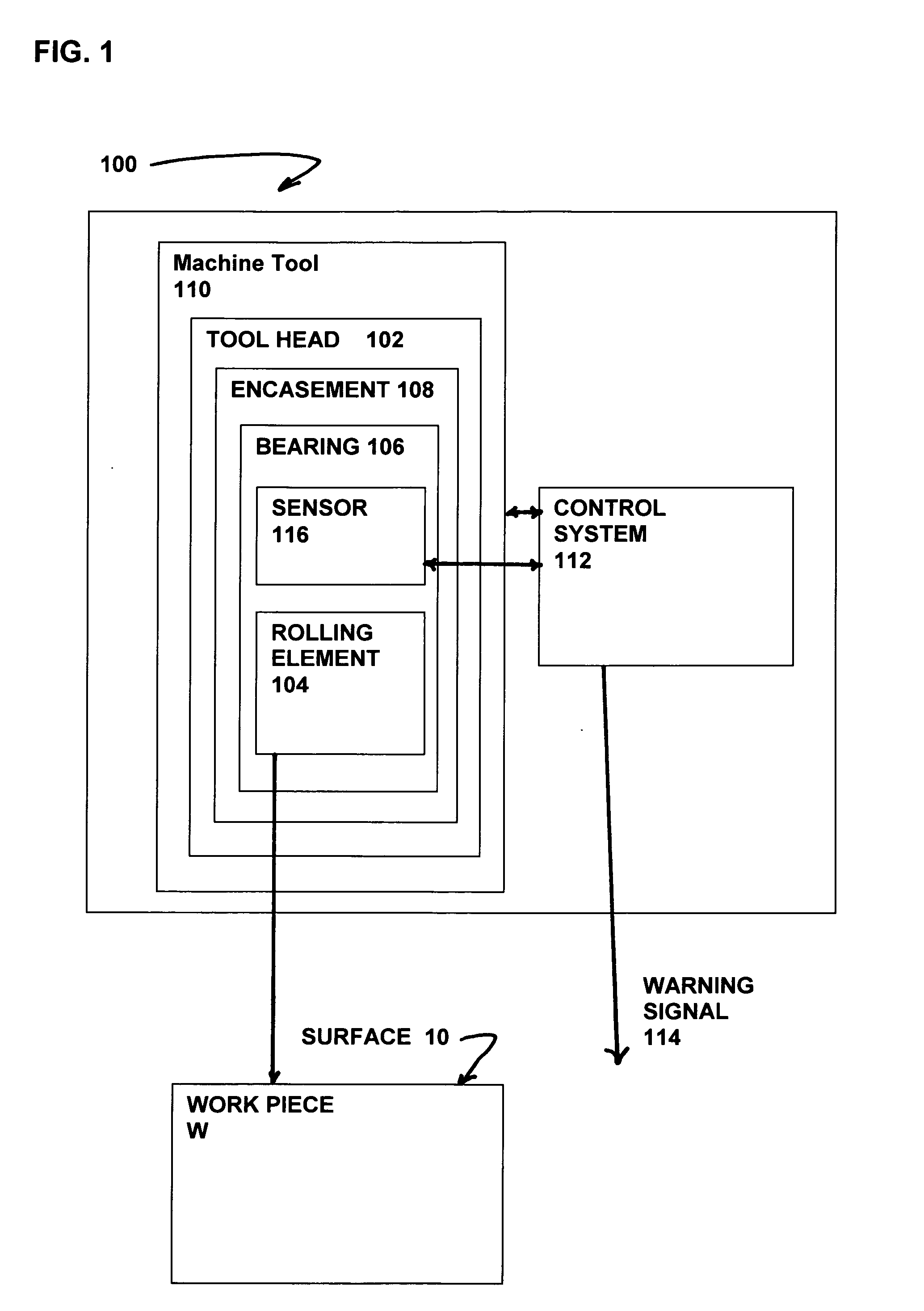
[0065]The present invention is a new and unique burnishing tool and method having a tool head comprising a rolling element, such as a roller or ball, supported by a bearing positioned within an outer relatively rigid encasement. The bearing is formed from a low friction polymer based bearing material, such as polytetrafluoroethylene (PTFE) based resins; or a ultra-high-molecular-weight polyethylene (UHMWPE or UHMW), also known as high-modulus polyethylene (HMPE); or high-performance polyethylene (HPPE); or another polymer material that provides a low coefficient of friction and is resistant to abrasion such that it is effective for supporting the rolling element.

[0066]It should now be understood that while polymer “plastic” bearings have been used for rotating shafts, linear bearings and similar applications. Such polymer bearings have not been used in burnishing tools for supporting rolling elements because of the limited compressive strength of the polymers used to form the bearin...


PUM

PropertyMeasurementUnit
surface areaaaaaaaaaaa
diameteraaaaaaaaaa
compressive yield strengthaaaaaaaaaa

Abstract

A burnishing tool and method for providing a surface treatment along the surface of a work piece, the burnishing tool having a tool head comprising a bearing for supporting a rolling element and an encasement for supporting the bearing. The bearing is formed from a self-lubricating polymer such as, but not limited to, polytetrafluoroethylene based resin, ultra-high-molecular-weight polyethylene based resin.

Description

BACKGROUND OF THE INVENTION[0001]The subject invention is directed to burnishing tools and methods for burnishing a work piece and more particularly, to new and novel burnishing tools and methods whereby a burnishing tool comprises a tool head having a low friction polymer support bearing.[0002]Ball, wheel, and roller burnishing tools with actively rolling elements are well known, and have been widely used for decades for surface finishing and sizing of metallic articles. Ball and roller burnishing is generally performed in a machine tool, often a lathe, as a final machining operation.[0003]For the purpose of improving the surface finish of a work piece, a rolling element is pressed against the surface of a work piece with sufficient force to plastically deform the high points and asperities or “tooling marks” left from prior machining or grinding. Using a suitable high-hardness rolling element and the appropriate force for the work piece material, elimination of the tooling marks c...

Claims


Application Information

Patent Timeline
Patent Type & Authority Applications(United States)
IPC IPC(8): B24B39/00
CPCY10T29/49776B24B39/00Y10T29/474B24B39/003Y10T29/47B23P9/02C21D7/08
Inventor PREVEY, MICHAELPREVEY, III, PAUL S.
Owner SURFACE TECH HLDG
Why Eureka
Try Eureka