Endotracheal tube cuff pressure regulator

Inactive Publication Date: 2012-08-16
OUTCOME SOLUTIONS
View PDF13 Cites 14 Cited by
  • Summary
  • Abstract
  • Description
  • Claims
  • Application Information

AI Technical Summary

Benefits of technology

[0008]The present invention is directed to a system and method for maintaining endotracheal cuff inflation with a source of constant air flow, eliminating the need to periodically reinflate the cuff with a syringe as in previous methods. Generally, the system is comprised of a pressure regulator adapted for attachment to a source of constant air flow, such as the air supply outlet of a hospital room, and to a tube connecting the regulator to an endotracheal cuff.
[0020]The air flow rate from some air supplies, such as the air supply obtained from the air supply outlet of a hospital room, may be greater that is required to maintain cuff inflation. If so, the air supply may be discharged through a flowmeter to reduce the air flow to an acceptable level. If a flowmeter is present, the regulator of the present invention is attached to the flowmeter instead of directly to the air supply outlet, with a flowmeter connector being used to connect the flowmeter and regulator, The flowmeter connector may include a first sleeve for attachment to the regulator and a second sleeve to receive the discharge end of a flowmeter. For ease of connection to some flowmeter connectors, the second sleeve may be flared.

Problems solved by technology

A disadvantage of the continuous pressurization of the cuff is that the cuff causes sloughing of the bronchial cells, and the pressure might disturb normal blood flow thus causing, in extreme cases, the cells to become necrotic.
On the other hand, if the pressure of the cuff is too low a pressure, the artificial respiration can be inhibited due to a leakage of anesthetic gas, oxygen or air.
Another disadvantage of the traditional cuff is that clinicians must intermittently check the cuff to avoid loss of cuff volume and integrity of the tracheal seal since, over time, the cuff loses its pressure.

Method used


Image

  • Endotracheal tube cuff pressure regulator
  • Endotracheal tube cuff pressure regulator
  • Endotracheal tube cuff pressure regulator

Examples


Embodiment Construction

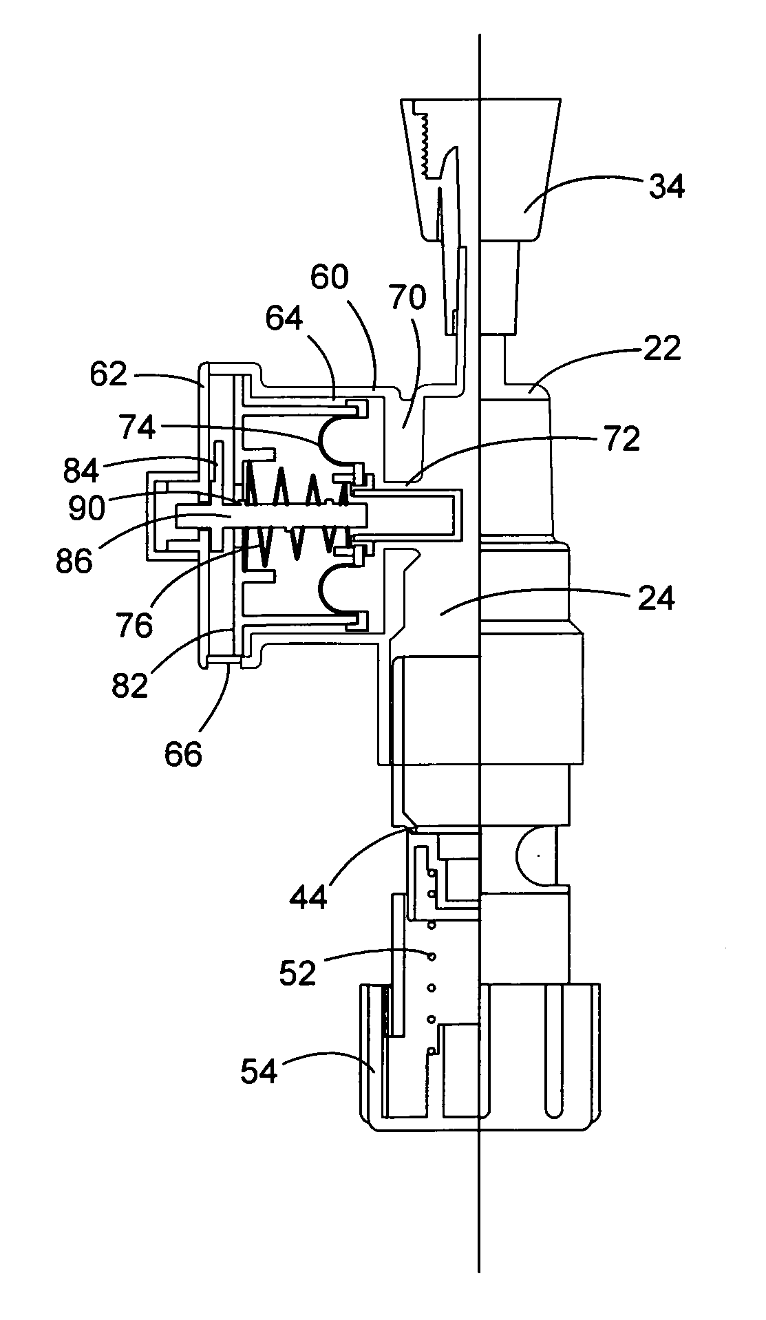
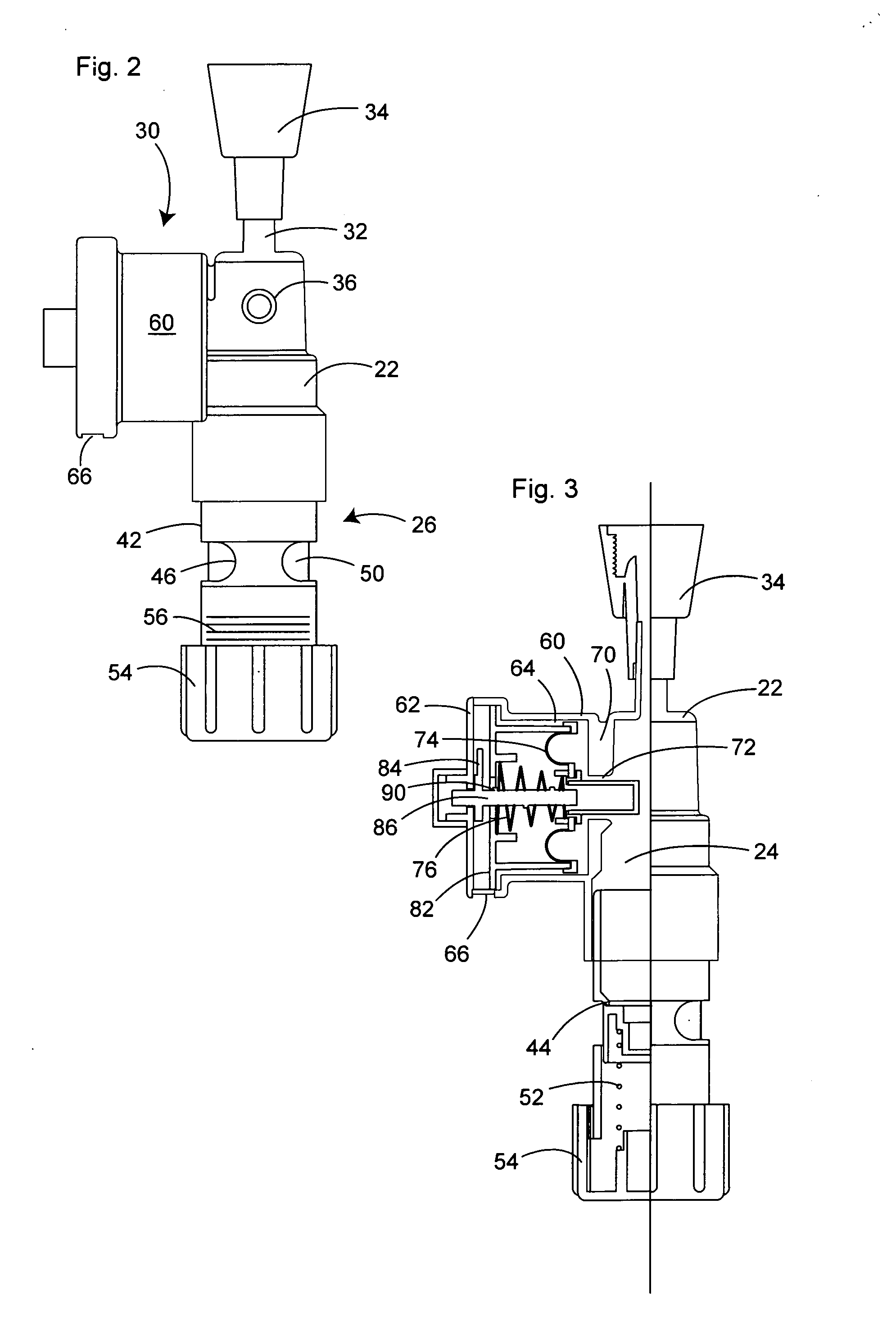
[0026]In the following description, terms such as horizontal, upright, vertical, above, below, beneath, and the like, are used solely for the purpose of clarity in illustrating the invention, and should not be taken as words of limitation. The drawings are for the purpose of illustrating the invention and are not intended to be to scale.

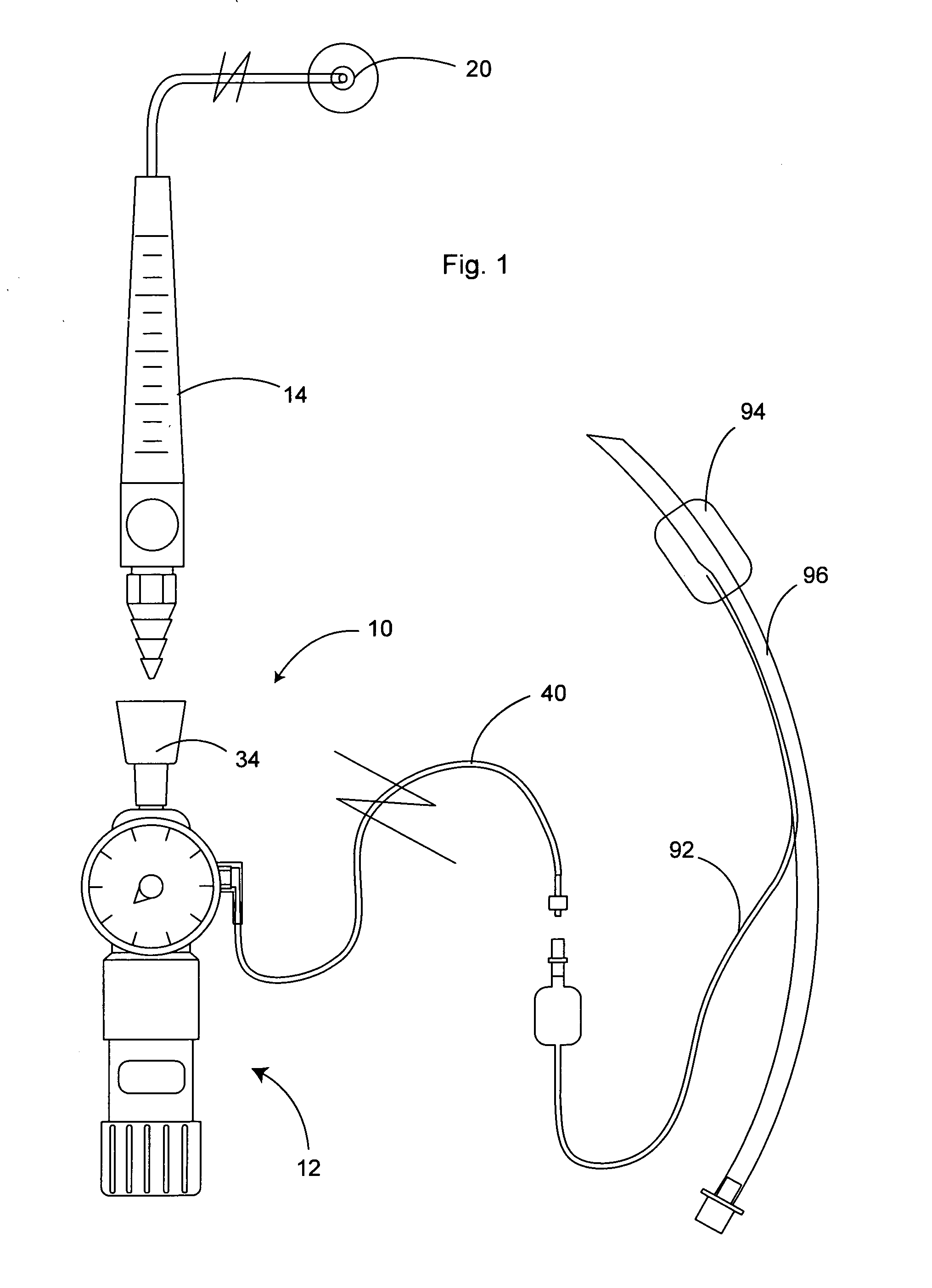
[0027]In the preferred embodiment described and illustrated, the regulator is connected through a flowmeter to the air source, since a flowmeter will be normally used to reduce the air flow to an acceptable level, e.g., for about 1 liters / minute to about 3 liters / minute. It will be understood, however, that the regulator may be connected directly to a constant air supply source which is at an acceptable air flow volume.

[0028]As best shown in FIG. 1, the preferred embodiment of the present system, generally 10, connects regulator, generally 12, between flowmeter, generally 14, and endotracheal tube, generally 16. Flowmeter 14 is in communication with ...


PUM


Abstract

An inflated endotracheal tube cuff maintained at a desired inflation using a constant air source. The constant air flow source is connected to a pressure regulator that is connected to the endotracheal tube cuff via the endotracheal tube cuff lumen. The regulator includes a bleed valve used to control the air pressure to the cuff so that a constant desired air pressure is maintained. The regulator may also include a manometer for visually displaying the pressure in the regulator, and thereby the cuff.

Description

BACKGROUND OF THE INVENTION[0001](1) Field of the Invention[0002]This invention relates to endotracheal tube systems, and more particularly to a method and apparatus for maintaining inflation of the cuff associated with the endotracheal tube at a desired inflation pressure utilizing a constant air flow from a pressurized air supply, such as the air discharge outlet commonly found in hospital rooms.[0003](2) Description of the Prior Art[0004]In the treatment of patients requiring breathing assistance, the use of an endotracheal tube for insertion into the trachea of the patient by way of the mouth, nose or a surgically created opening is common. The endotracheal tube is connected to a breathing apparatus such as a respirator which operates on repeated cycles of alternative inspiration and expiration. Upon inspiration, air or anesthesia or oxygen is supplied under pressure to the lungs, and upon expiration the air is allowed to exhaust from the lungs. The tube is typically provided wi...

Claims


Application Information

Patent Timeline
IPC IPC(8): A61M16/04
CPCA61M2205/3334A61M16/044
Inventor HOWARD, WILLIAM R.
Owner OUTCOME SOLUTIONS
Why Eureka
Try Eureka