Radiological image detection apparatus

Inactive Publication Date: 2012-08-16
FUJIFILM CORP
View PDF6 Cites 2 Cited by
  • Summary
  • Abstract
  • Description
  • Claims
  • Application Information

AI Technical Summary

Benefits of technology

[0015]According to the radiological image detection apparatus, it is possible to enhance the adhesion between a sensor panel and

Problems solved by technology

In a radiological image detection apparatus in which a scintillator is provided on the substrate side of a sensor panel, there is a fear that the scintillator may be separated from the sensor panel.
As a result, warping caused by a temperature change generates stress in a bonding interface between the scintillator and the sensor panel.
However, since the substrate of the sensor panel is interposed between the scintillator and a photoelectric conversion element group of the sensor panel, thickening the adhesive layer brings about the further increase in the distance between the scintillator and the photoelectric conversion element group.
Thus, t

Method used


Image

  • Radiological image detection apparatus
  • Radiological image detection apparatus
  • Radiological image detection apparatus

Examples


Example

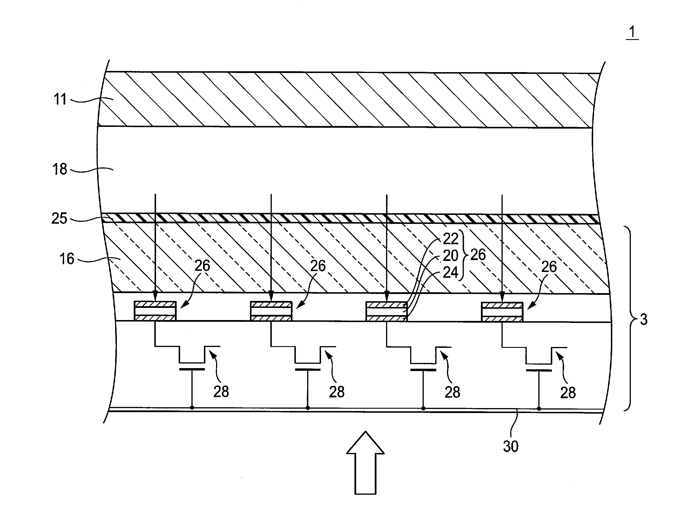
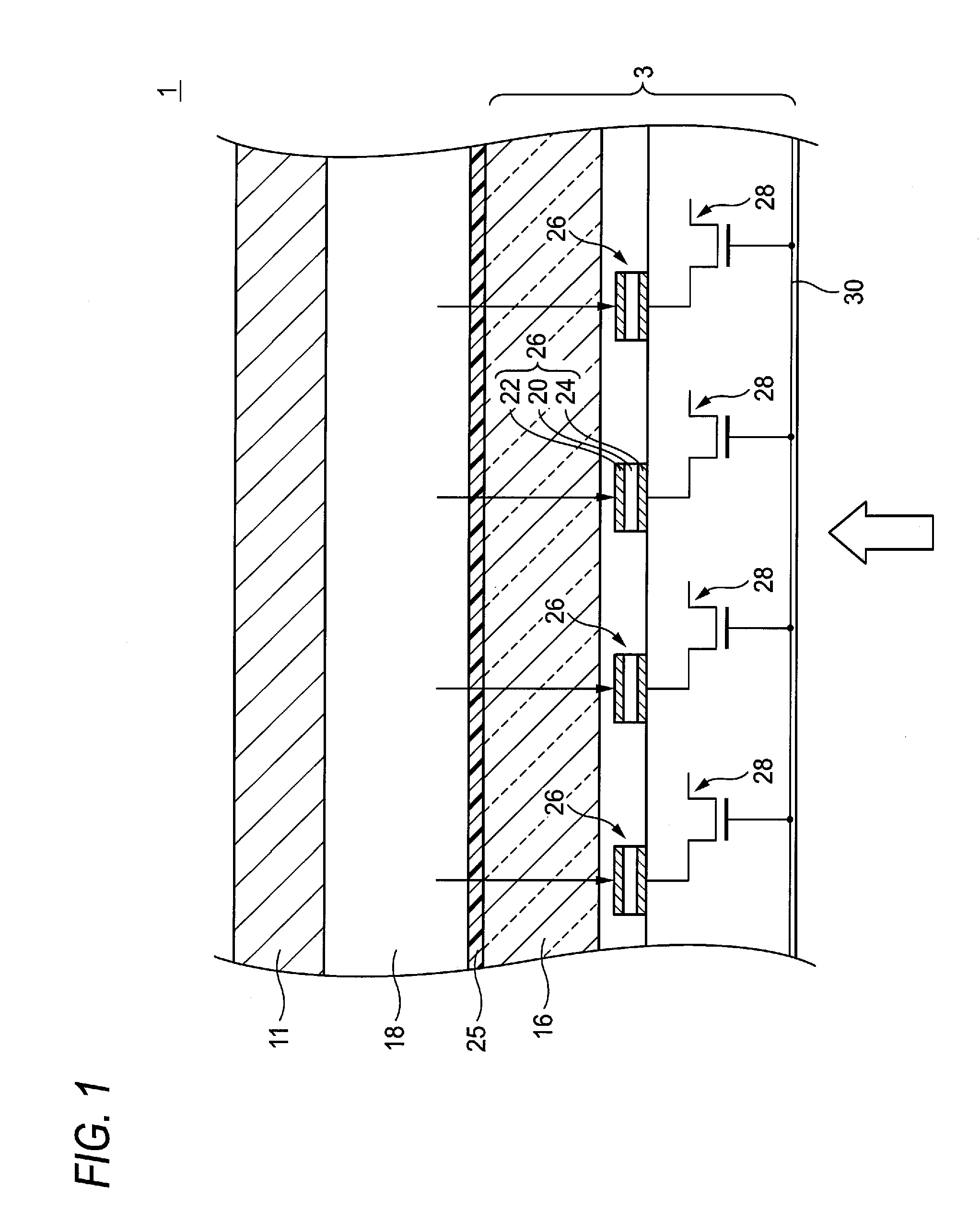
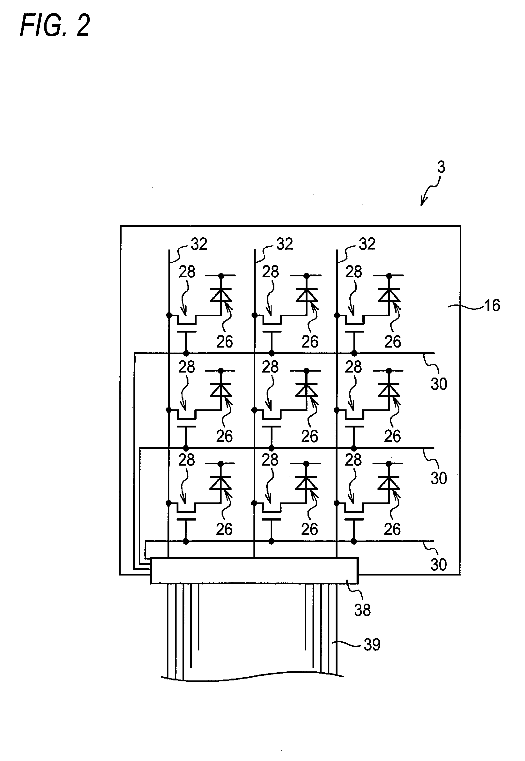
[0024]FIG. 1 shows a configuration of an example of a radiological image detection apparatus for explaining a mode for carrying out the invention. FIG. 2 shows a configuration of a sensor panel of the radiological image detection apparatus in FIG. 1.

[0025]A radiological image detection apparatus 1 has a scintillator (phosphor) 18 which emits fluorescence when exposed to radiation, and a sensor panel 3 which detects the fluorescence of the scintillator 18.

[0026]The sensor panel 3 has an insulating substrate 16 which can transmit the fluorescence of the scintillator 18. A plurality of photoelectric conversion elements 26 photoelectrically converting the fluorescence of the scintillator 18, and switching devices 28 consisting of TFTs (Thin Film Transistors) are provided on the insulating substrate 16 so as to be arrayed two-dimensionally.

[0027]Each photoelectric conversion element 26 consists of a photoconductive layer 20 which generates electric charges when light is incident thereon,...


PUM


Abstract

A radiological image detection apparatus includes: a phosphor which contains a fluorescent material emitting fluorescence when exposed to radiation; and a sensor panel which detects the fluorescence; in which the sensor panel has a substrate and a group of photoelectric conversion elements provided on one side of the substrate; the phosphor adheres closely to an opposite surface of the substrate to the side where the group of photoelectric conversion elements are provided; and an irregular structure is formed in the surface of the substrate to which the phosphor adheres closely.

Description

CROSS-REFERENCE TO RELATED APPLICATIONS[0001]This application is based on and claims priority under 35 USC 119 from Japanese Patent Application No. 2011-030225 filed on Feb. 15, 2011; the entire content of which is incorporated herein by reference.BACKGROUND[0002]1. Technical Field[0003]The present invention relates to a radiological image detection apparatus.[0004]2. Related Art[0005]In recent years, a radiological image detection apparatus using an FPD (Flat Panel Detector) for detecting a radiological image and generating digital image data has been put into practical use. The radiological image detection apparatus has been being widely used rapidly for the reason that an image can be confirmed in real time as compared with a background-art imaging plate. There are various systems for such a radiological image detection apparatus. An indirect conversion system has been known as one of the systems.[0006]A radiological image detection apparatus using the indirect conversion system ...

Claims


Application Information

Patent Timeline
IPC IPC(8): G01T1/20
CPCG01T1/202
Inventor KANEKO, YASUHISANAKATSUGAWA, HARUYASU
Owner FUJIFILM CORP
Why Eureka
Try Eureka