Electric conductivity-based biosensor

Inactive Publication Date: 2012-06-14
NATIONAL TSING HUA UNIVERSITY
View PDF4 Cites 2 Cited by
  • Summary
  • Abstract
  • Description
  • Claims
  • Application Information

AI Technical Summary

Benefits of technology

[0006]To achieve the abovementioned objectives, the present invention proposes an electric conductivity-based biosensor, which comprises a substrate, two electric-conduction electrodes, an antibody adhesion layer and a plurality of antibodies. The two electric-conduction electrodes are arranged on the substrate. The antibody adhesion layer is arranged on a region of the substrate, which is between the two electric-conduction electrodes. The antibody adhesion layer includes a first surface contacting the substrate and a second surface opposite to the first surface. The plurality of antibodies is arranged on the second surface of the antibody adhesion layer. A plurality of tested objects is connected with the antibodies to form an electric-conduction group between the two electric-conduction electrodes. The antibody adhesion layer enhances adhesion between the antibodies and the substrate, whereby the antibodies are fi

Problems solved by technology

However, the diffraction apparatus have complicated structure and expensive cost.
Further, optical examination demands higher environmental restrictions.
The examination results would be affected if the environm

Method used


Image

  • Electric conductivity-based biosensor
  • Electric conductivity-based biosensor
  • Electric conductivity-based biosensor

Examples


Example

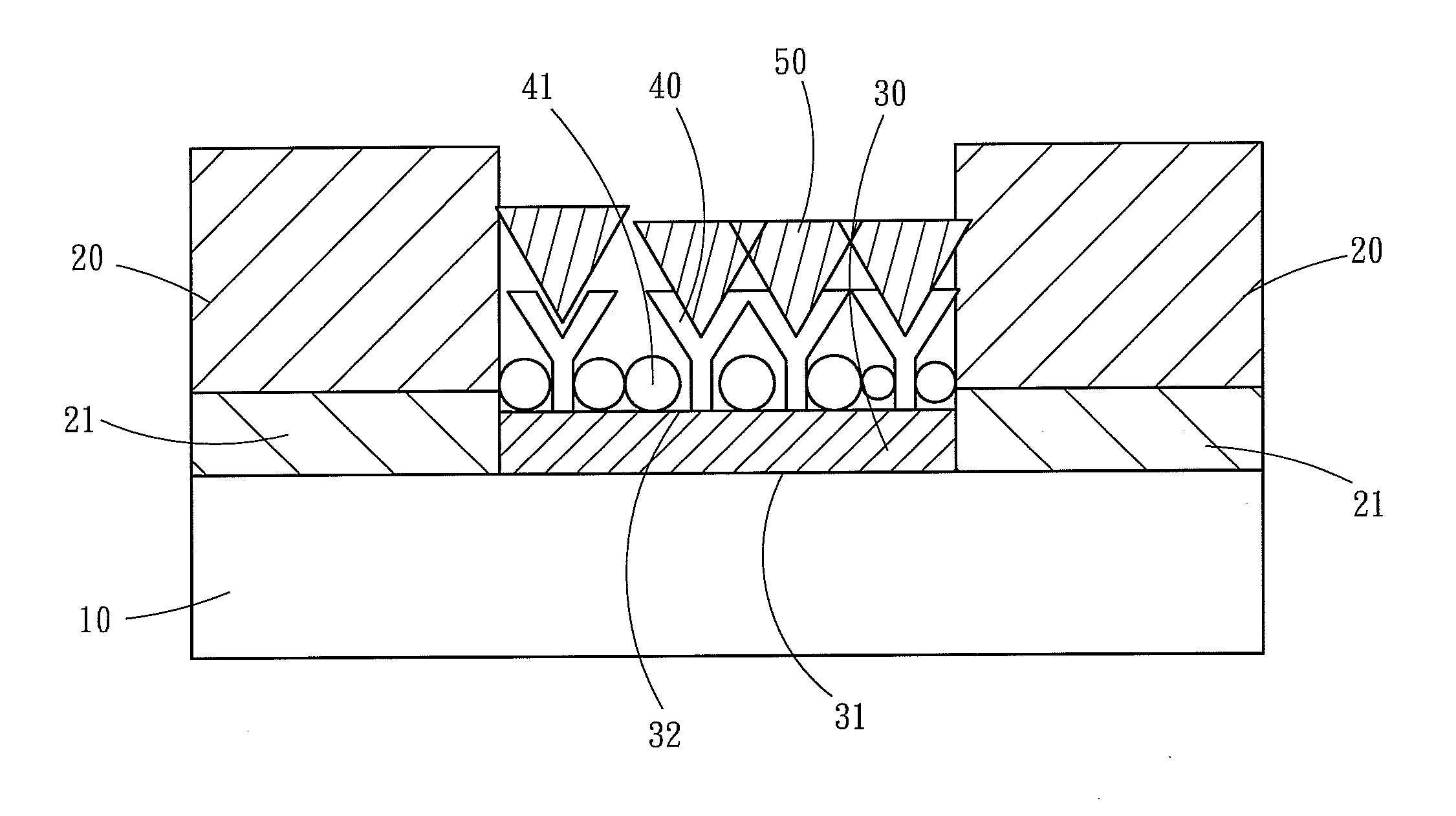
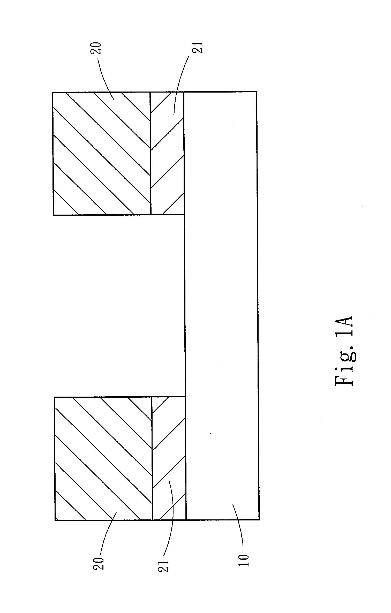
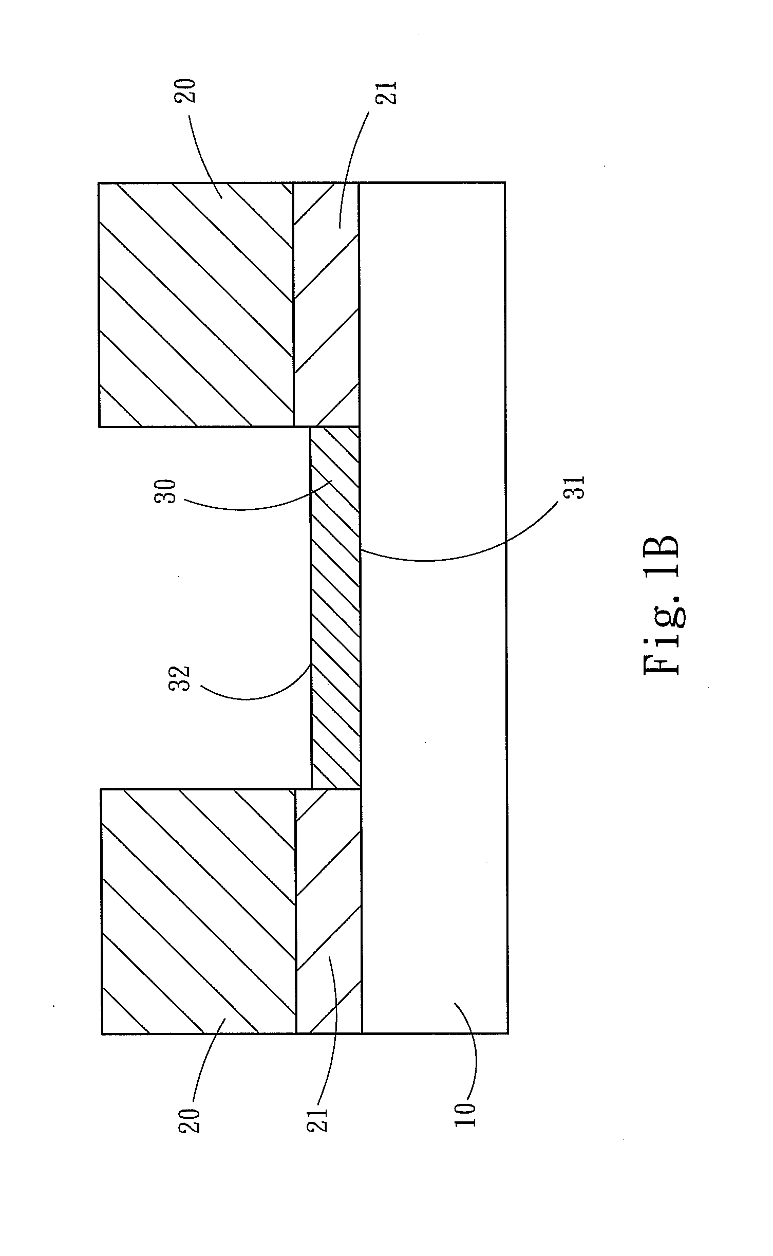
[0010]The technical contents of the present invention are described in detail in cooperation with the drawings below. Refer to FIGS. 1A to 1E for a series of cross-sectional views showing the process of fabricating an electric conductivity-based biosensor according to one embodiment of the present invention. The biosensor of the present invention comprises a substrate 10, two electric-conduction electrodes 20, an antibody adhesion layer 30 and a plurality of antibodies 40. The two electric-conduction electrodes 20 are separately arranged on the substrate 10. The antibody adhesion layer 30 is arranged on a region of the substrate 10, which is between the two electric-conduction electrodes 20. The antibody adhesion layer 30 includes a first surface 31 contacting the substrate 10 and a second surface 32 opposite to the first surface 31. The plurality of antibodies 40 is arranged on the second surface 32 of the antibody adhesion layer 30 and connected with a plurality of tested objects ...


PUM


Abstract

An electric conductivity-based biosensor electrochemically detects the concentration of tested objects via measuring impedance or capacitance variation of the tested objects. The biosensor comprises a substrate, two electric-conduction electrodes arranged on the substrate, an antibody adhesion layer arranged on a region of the substrate and a plurality of antibodies arranged on the antibody adhesion layer. The antibody adhesion layer is between the two electric-conduction electrodes. The antibodies are connected with a plurality of tested objects. The tested objects connected with the antibodies form an electric-conduction group contacting the two electric-conduction electrodes. The concentration of the tested objects can be provided via measuring impedance or capacitance between the two electric-conduction electrodes.

Description

FIELD OF THE INVENTION[0001]The present invention relates to a biosensor, particularly to an electric conductivity-based biosensor.BACKGROUND OF THE INVENTION[0002]Biosensors can effectively quantify results of physical examination and provide exact values for health evaluation. A biosensor integrates a biological recognition element and a transduction element to convert biological signals into quantifiable electronic signals. Biosensors may be categorized into bioaffmity sensors and biocatalytic sensors according to the types of biological recognition elements. Biosensors may be categorized into electrochemical type, optical type, piezoelectric type, FET (Field Effect Transistor) and OTFT (Organic Thin Film Transistor) biosensors according to the types of transduction elements.[0003]A U.S. Pat. No. 7,485,453, disclosed “Diffraction-Based Diagnostic Devices”, wherein the concentration of a tested enzyme is detected with an optical method. However, the diffraction apparatus have comp...

Claims


Application Information

Patent Timeline
IPC IPC(8): G01N27/00
CPCG01N27/125
Inventor CHUANG, YA-HSUANLIU, KUO-LIANGYEW, TRI-RUNG
Owner NATIONAL TSING HUA UNIVERSITY
Why Eureka
Try Eureka