Controller for a power converter and method of operating the same

a technology of control loop and power converter, which is applied in the direction of dc-ac conversion without reversal, power conversion system, electrical apparatus, etc., can solve the problem of introducing a final phase delay within the control loop

Inactive Publication Date: 2012-08-16
SIEMENS AG
View PDF6 Cites 18 Cited by
  • Summary
  • Abstract
  • Description
  • Claims
  • Application Information

AI Technical Summary

Benefits of technology

[0008]This aspect of the invention is based on the idea that a delay between taking of the feedback signal and updating the switching pattern can be reduced while maintaining u

Problems solved by technology

However a finite phase delay is introduced within the control loop, due to the delay between

Method used


Image

  • Controller for a power converter and method of operating the same
  • Controller for a power converter and method of operating the same
  • Controller for a power converter and method of operating the same

Examples


Embodiment Construction

[0041]The illustration in the drawings is schematic. It is noted that in different figures, similar or identical elements are provided with the same reference signs and the description of these elements is not repeated upon further occurrence of these elements.

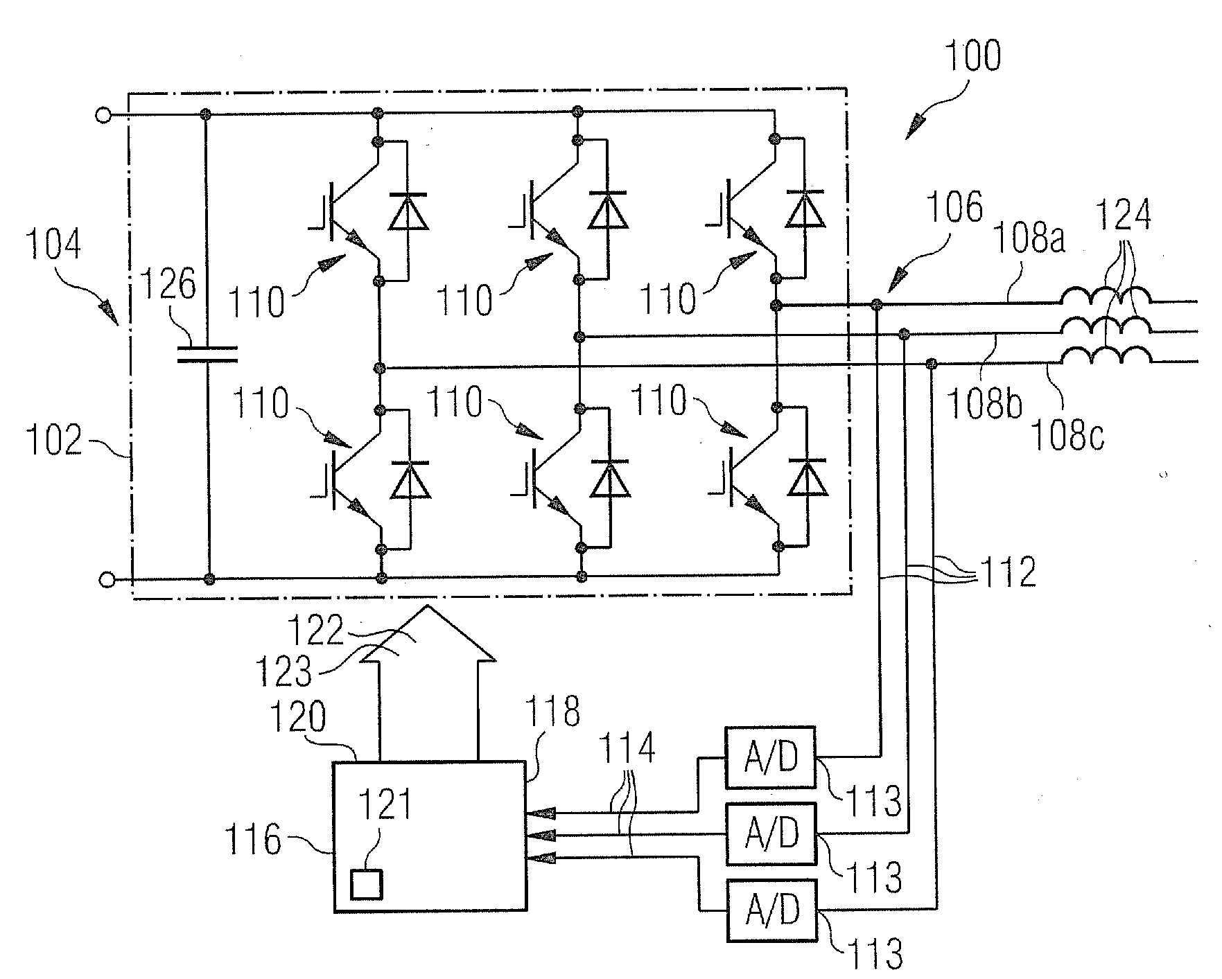
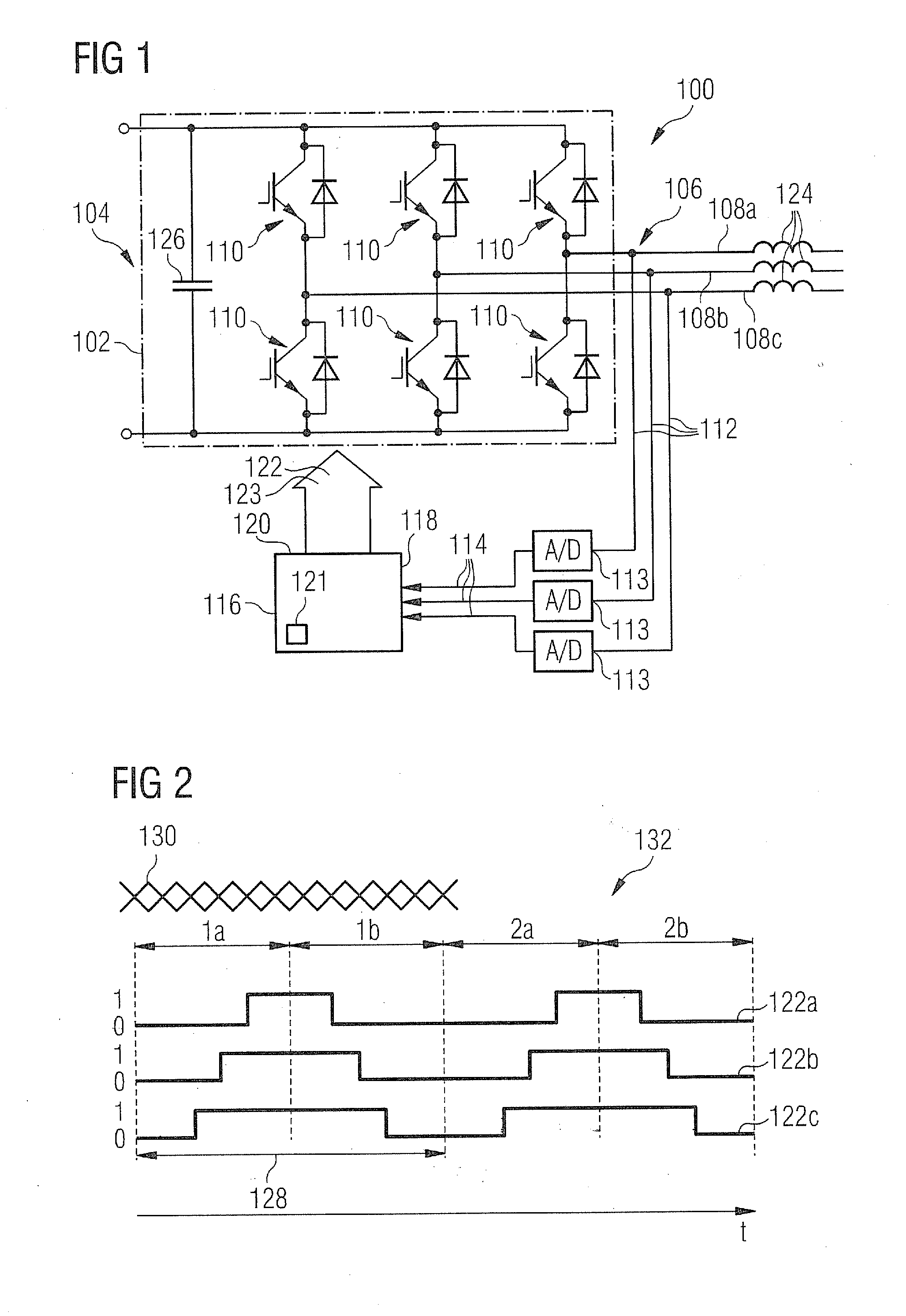
[0042]FIG. 1 shows a converter device 100 in accordance with embodiments of the herein disclosed subject matter. In accordance with an embodiment, the converter device 100 comprises a converter, generally indicated at 102. The converter 102 has an input 104 for receiving an input voltage, e.g. a DC voltage and an output 106 for providing an output power by the switching operation of the converter 102. In an embodiment, the output power is a three-phase power. Accordingly, the output 106 comprises three output lines 108a, 108b, 108c corresponding to the three phases.

[0043]In accordance with an embodiment, the converter comprises a pulse width modulation bridge having two switching elements 110 per phase. The switching elements ...


PUM


Abstract

There is provided a controller for a converter and a respective method of operating such a controller. The converter receives an input power and provides an output power by a switching operation wherein in an embodiment the output power has at least two phases. The controller includes an input for receiving a feedback signal depending on the output power of the converter, and an output for providing a control signal to the converter to thereby control the switching operation of the converter. The control signal corresponds to a switching pattern that is updated in response to the feedback signal. The control signal includes a harmonic compensation signal which reduces higher harmonics in the output power, the higher harmonics originating from a time delay between taking the feedback signal and the updating of the switching pattern.

Description

CROSS REFERENCE TO RELATED APPLICATIONS[0001]This application claims priority of European Patent Office application No. 11154344.3 EP filed Feb. 14, 2011. All of the applications are incorporated by reference herein in their entirety.FIELD OF INVENTION[0002]The present invention relates to the field of power converters.BACKGROUND OF INVENTION[0003]Within closed loop control systems which use sampled feedback data there is a finite delay between sampling the feedback variable and the actuator changing in response to these feedback signals. For example, in case of a three phase voltage sourced converter, the feedback variables are the three phase currents, and the actuator is in effect the pulse width modulation (PWM) bridge which changes the three phase voltage in amplitude and phase to control the three phase currents.[0004]Typically in fixed switching frequency PWM schemes the current is sampled many times during a complete PWM period (PWM period=1 / (switching frequency)) and the av...

Claims


Application Information

Patent Timeline
IPC IPC(8): H02M1/12
CPCH02M1/12H02M2001/0009H02M7/5395H02M7/53873H02M1/0009H02M7/48
Inventor BROGAN, PAUL BRIANFULCHER, ROBERT VERNON
Owner SIEMENS AG
Why Eureka
Try Eureka