Hybrid vehicle drive system and method and idle reduction system and method

Inactive Publication Date: 2012-08-16
ODYNE SYST
View PDF17 Cites 91 Cited by
  • Summary
  • Abstract
  • Description
  • Claims
  • Application Information

AI Technical Summary

Benefits of technology

[0014]Yet another embodiment relates to a method of operating a hybrid vehicle drive system. The drive system includes a first prime mover, a first prime mover driven transmission, a second prime mover, a first rechargeable energy source, a component, and an accessory. The second prime mover can effect the motion of a drive shaft alone or in combina

Problems solved by technology

One limitation of this system is that the second prime mover is typically positioned between the first prime mover and the transmission, creating the need to reposition existing drive train components.
One limitation of this system is that while it allows the electric motor to provide power to a drive shaft through the PTO, it does not provide power to a hydraulic pump for operation of vehicle mounted hydraulic components and equipment.
The system also does not allow a hydraulic motor/pump to be driven by either the internal combustion engine or by the electric motor/generator, nor does it allow the hydraulic motor/pu

Method used


Image

  • Hybrid vehicle drive system and method and idle reduction system and method
  • Hybrid vehicle drive system and method and idle reduction system and method
  • Hybrid vehicle drive system and method and idle reduction system and method

Examples


Embodiment Construction

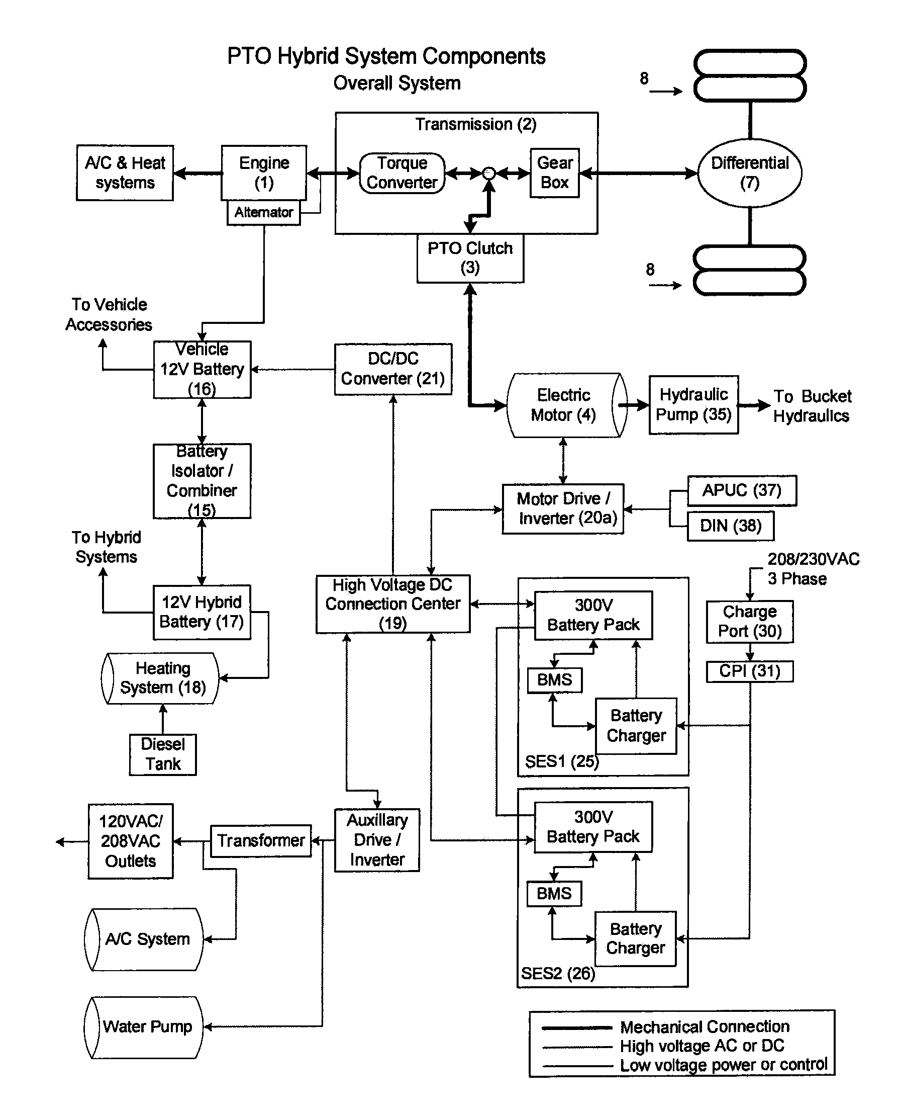
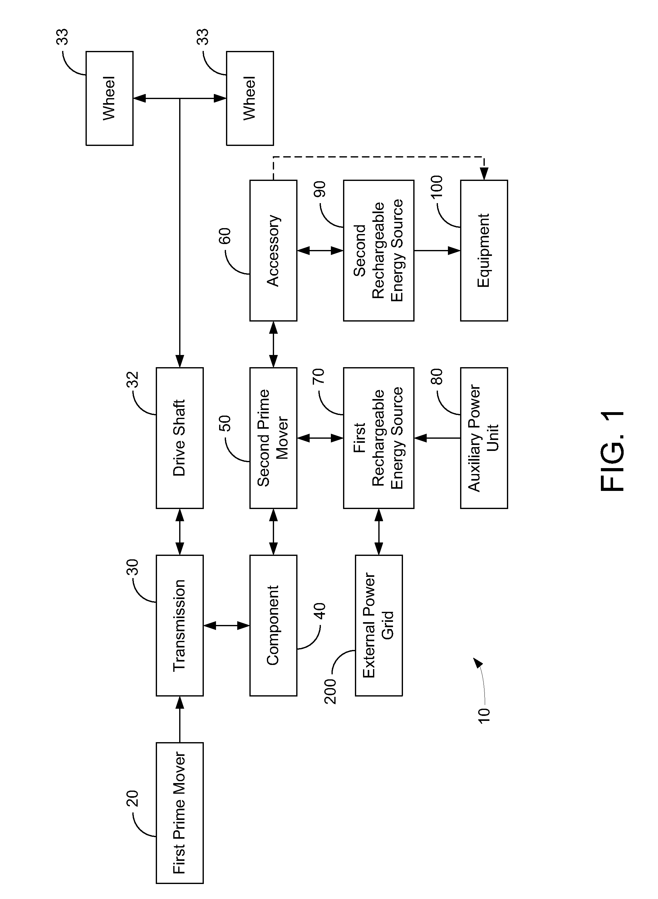
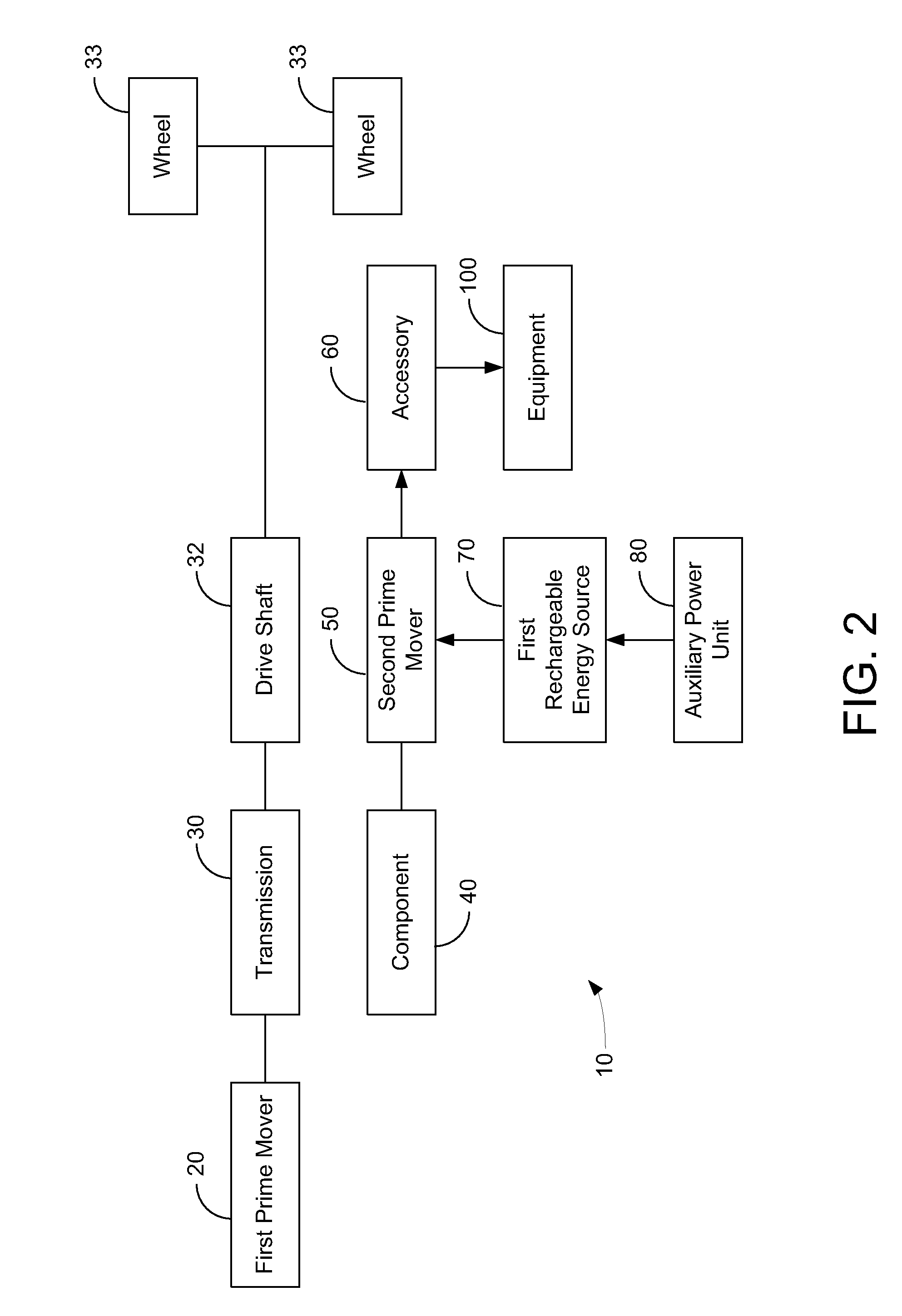
[0056]Hybrid vehicle drive systems according to several possible embodiments are presented. One feature of one exemplary embodiment of the hybrid vehicle drive system is that a drive shaft can be powered singly or in any combination by a first prime mover, a second prime mover, and an accessory. Preferred embodiments incorporate hydraulic systems into the hybrid vehicle drive system for optimal energy storage and usage. It is noted that the term motor as used herein refers to a motor / generator or motor / pump and is not limited to a device that performs only motor operations.

[0057]Another feature of one exemplary embodiment of the system is that when a power take-off (PTO) configured to be engaged or disengaged while a transmission is moving is used, any unneeded drive system components other than a first prime mover can be entirely disconnected from the drive train, reducing inefficiencies and wear in situations where the different portions of the system do not need to interact, such...


PUM


Abstract

One embodiment relates to a hybrid vehicle drive system for a vehicle including a first prime mover, a first prime mover driven transmission, a rechargeable power source, and a PTO. The hybrid vehicle drive system further includes a hydraulic motor in direct or indirect mechanical communication with the PTO and an electric motor in direct or indirect mechanical communication with the hydraulic motor. The electric motor can provide power to the prime mover driven transmission and receive power from the prime mover driven transmission through the PTO. The hydraulic motor can provide power to the prime mover driven transmission and receive power from the prime mover driven transmission through the PTO.

Description

CROSS-REFERENCES TO RELATED APPLICATIONS[0001]The present application claims the benefit of and priority to and is also a continuation-in-part of U.S. application Ser. No. 12 / 130,888 filed on May 30, 2008(96637-106) which is incorporated herein by reference in its entirety and claims the benefit of and priority to U.S. Provisional Application Ser. No. 60 / 979,755 filed Oct. 12, 2007(96637-103), which is incorporated herein by reference in its entirety, and U.S. Provisional Application Ser. No. 61 / 014,406 filed Dec. 17, 2007(96637-104) which is incorporated herein by reference in its entirety. The present application is also a continuation-in-part of U.S. application Ser. No. 12 / 217,407 filed on Jul. 3, 2008(96637-115), which is incorporated herein by reference in its entirety, and claims the benefit of and priority to U.S. Provisional Application Ser. No. 60 / 959,181 filed Jul. 12, 2007(INV-79701 / US1 / X) which is incorporated herein by reference in its entirety and U.S. Provisional App...

Claims


Application Information

Patent Timeline
IPC IPC(8): F04B49/06
CPCB60K6/12Y02T10/70B60K17/28B60K25/00B60L1/00B60L1/003B60L1/006B60L1/02B60L7/14B60L11/005B60L11/14B60L11/1816B60L11/1822B60L11/184B60L11/1842B60L11/1844B60L11/1848B60L11/1857B60L11/1866B60L11/1868B60L11/1874B60L11/1875B60L2210/10B60L2210/40B60L2240/445B60L2240/545B60W10/06B60W10/08B60W10/30B60W20/00B60Y2200/14Y02T10/6208Y02T10/6221Y02T10/6269Y02T10/6278Y02T10/6286Y02T10/7077Y02T90/16Y02T10/7005Y02T10/7241Y02T10/7022Y02T10/7066Y02T10/7061Y02T10/7072Y02T10/7216Y02T90/163Y02T90/169Y02T90/124Y02T90/121Y02T90/14Y02T90/128Y02T90/127Y04S10/126Y04S30/14Y02E60/721B60K6/48B60W20/14B60L53/14B60L50/40B60L50/16B60L53/80B60L53/64B60L55/00B60L53/63B60L53/665B60L58/16B60L58/22B60L58/20B60L58/26B60L58/27Y10S903/93Y02E60/00Y02T10/62Y02T10/72Y02T90/12Y02T90/167B60W20/10B60W10/02B60W10/196B60W10/24B60W20/40B60W30/18172B60W30/19B60W30/20
Inventor DALUM, JOSEPH THOMASAMBROSIO, JOSEPH MARIO
Owner ODYNE SYST
Why Eureka
Try Eureka