Elements of drive power transfer belt of belt-drive continuously variable transmission for vehicle

a technology of transmission belt and drive power, which is applied in the direction of driving belt, v-belt, belt/chain/gearing, etc., can solve the problems of undesirable behavior and motion of elements, noise and reduced efficiency, etc., and achieve the effect of reducing power loss

Active Publication Date: 2012-08-16
TOYOTA JIDOSHA KK +1
View PDF9 Cites 6 Cited by
  • Summary
  • Abstract
  • Description
  • Claims
  • Application Information

AI Technical Summary

Benefits of technology

[0019]Further, the set of elements of the foregoing aspect of the invention may be such that the diameter of the projection decreases toward the tip of the projection from the other side of the element, and the element having said projection is located on an inner side of an arc that is drawn about a rocking center about which said element rocks relative to the element adjacent to said element, as viewed in an axial direction of the pulleys, such that the arc runs through a position at a base of said projection, the position being most distant from the rocking center. According to this structure, for example, when the projection slides, in the longitudinal direction of the drive power transfer belt, into the recess mating with it as the element having the same projection rocks about the rocking center at the drive pulley belt leaving position, the drive pulley belt entering position, the driven pulley belt entering position, or the driven pulley belt leaving position, the rubbing between the outer peripheral face of the projection and the inner peripheral face of the recess can be reduced, resulting in a decrease in the power loss that is caused by such rubbing.

Problems solved by technology

Therefore, if the opposed sides of the elements adjacent to each other are not sufficiently upright and parallel to each other when they are stacked on each other in the element thickness direction, an undesirable behavior or motion of each element may occur, resulting in noises and reduced efficiencies.
If the radial gap between the projection 514 and the recess 512 is very large, for example, the elements 510 stacked on each other can not be sufficiently inhibited from moving upward, downward, leftward, and rightward in directions parallel or substantially parallel to the opposed sides of the elements 510 in the belt-riding section at one of the pulleys and the belt-riding section at the other, and this results in undesirable behaviors and motions of the elements 510.

Method used


Image

  • Elements of drive power transfer belt of belt-drive continuously variable transmission for vehicle
  • Elements of drive power transfer belt of belt-drive continuously variable transmission for vehicle
  • Elements of drive power transfer belt of belt-drive continuously variable transmission for vehicle

Examples


Embodiment Construction

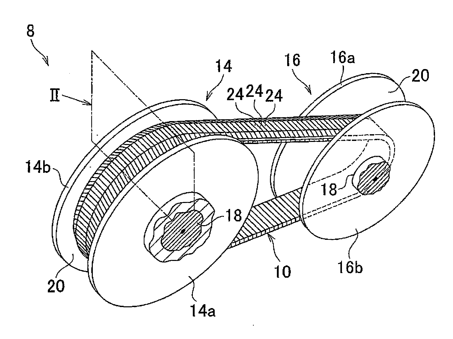
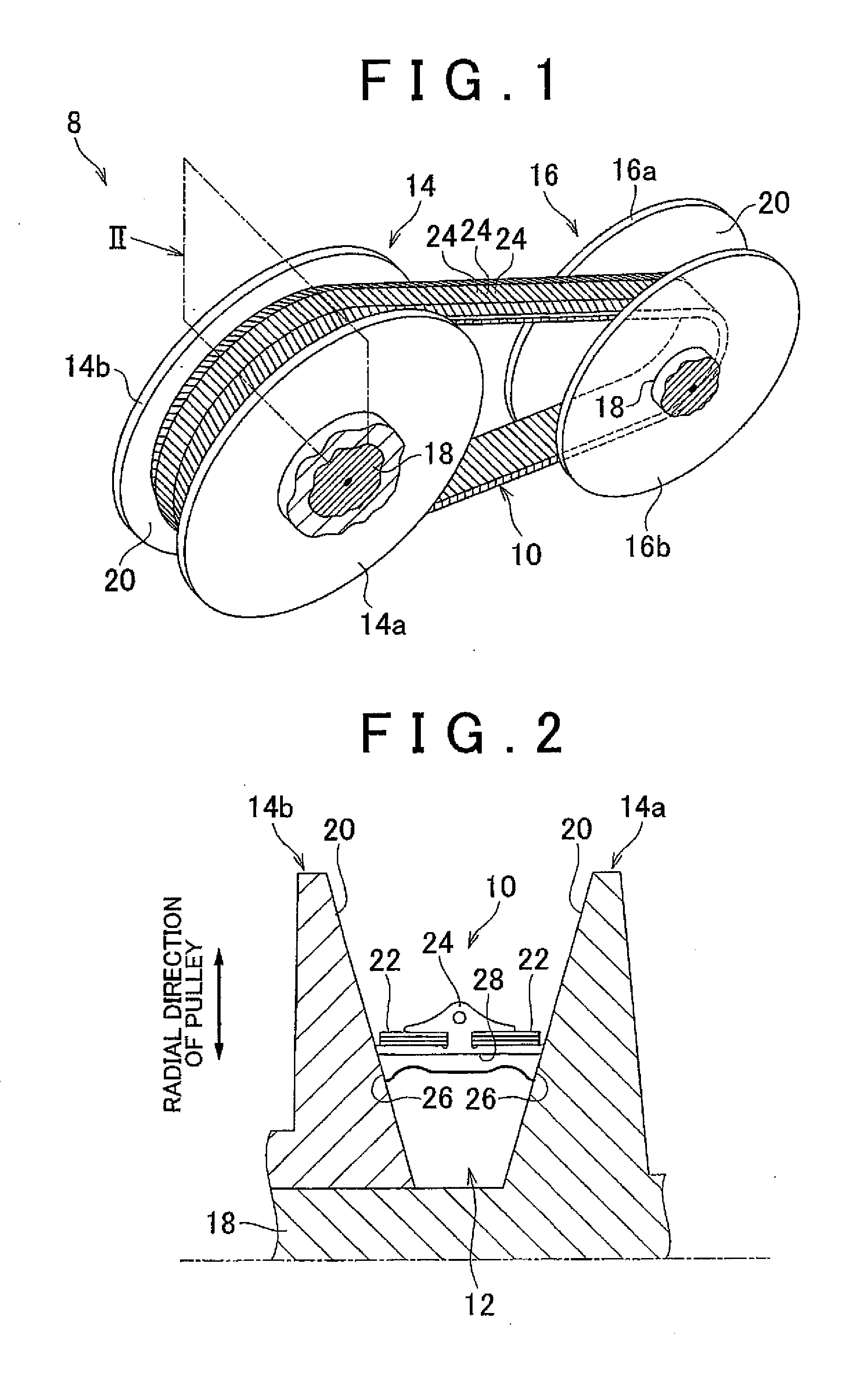
[0046]Hereinafter, en example embodiment of the invention will be described in detail with reference to the drawings. FIG. 1 is a perspective view illustrating, by way of example, a state where a drive power transfer belt 10 to which the invention is applied is set in a vehicle belt-drive continuously variable transmission 8 (will hereinafter be referred to as “the belt-drive continuously variable transmission 8”). FIG. 2 is a sectional view taken along the plane indicated by the arrow II in FIG. 1, showing cross sections of the drive power transfer belt 10 and its periphery. Referring to FIGS. 1 and 2, the drive power transfer belt 10 is a compression type drive power transfer belt (metallic belt) that is wound on a first pulley 14 and a second pulley 16 that are rotatable, respectively, about two parallel axes and that each have a V-groove 12 which is provided at the radially outer side of the pulley and of which the width is variable. The first pulley (first sheave pair) 14 is an...


PUM


Abstract

Provided are elements arranged along a ring of a drive power transfer belt wound on pulleys of a belt-drive continuously variable transmission. Each element has a recess at one side of the element and a projection projecting from the other side to fit into the recess of the adjacent element. The projection has a first engagement portion provided at its base side such that a predetermined engagement gap is created on the radially outer side when the projection fits in the recess of the adjacent element, and a second engagement portion provided at the tip side of the projection and decreasing in diameter toward the tip of the projection from the first engagement portion. The gradient with which the diameter of the second engagement portion decreases is larger than the gradient with which the diameter of the first engagement portion decreases toward the tip of the projection.

Description

INCORPORATION BY REFERENCE[0001]The disclosure of Japanese Patent Application No. 2011-029345 filed on Feb. 15, 2011 including the specification, drawings and abstract is incorporated herein by reference in its entirety.BACKGROUND OF THE INVENTION[0002]1. Field of the Invention[0003]The invention relates to the structure of elements used as parts of a drive power transfer belt wound on a pair of pulleys used in a belt-drive continuously variable transmission for vehicles and each having a variable-width groove.[0004]2. Description of Related Art[0005]A belt-drive continuously variable transmission is known which is provided on a power transfer path and which is constituted of a pair of pulleys each having a variable-width groove and a drive power transfer belt having a plurality of elements that are compressed at each pulley in a sandwiching manner and that are arranged in series on looped rings in the direction corresponding to the direction in which the thickness of each element i...

Claims


Application Information

Patent Timeline
Patent Type & Authority Applications(United States)
IPC IPC(8): F16G5/18
CPCF16G5/16
Inventor YAMANAKA, KENNAGASAWA, YUJITARUTANI, ICHIRO
Owner TOYOTA JIDOSHA KK
Why Eureka
Try Eureka