

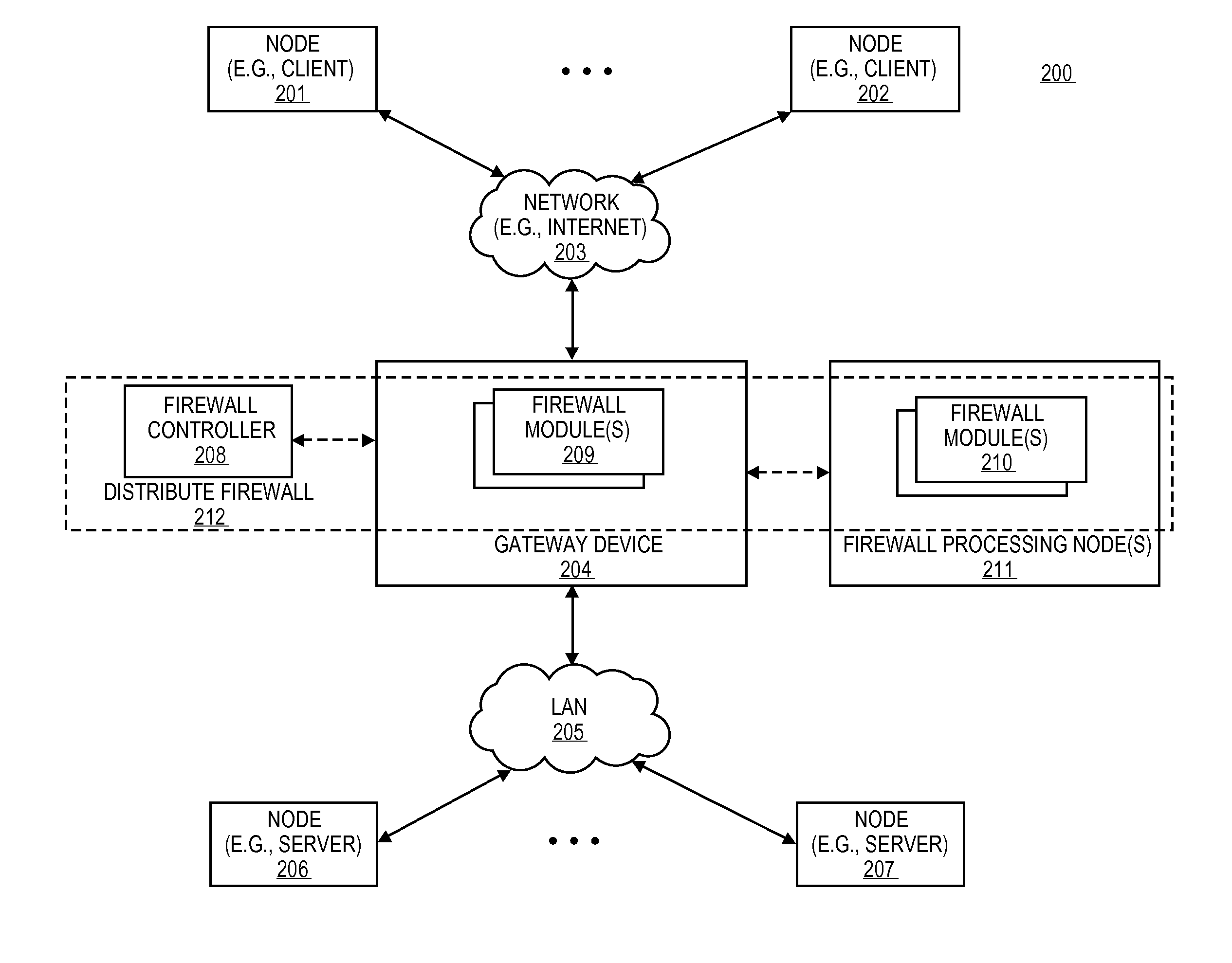
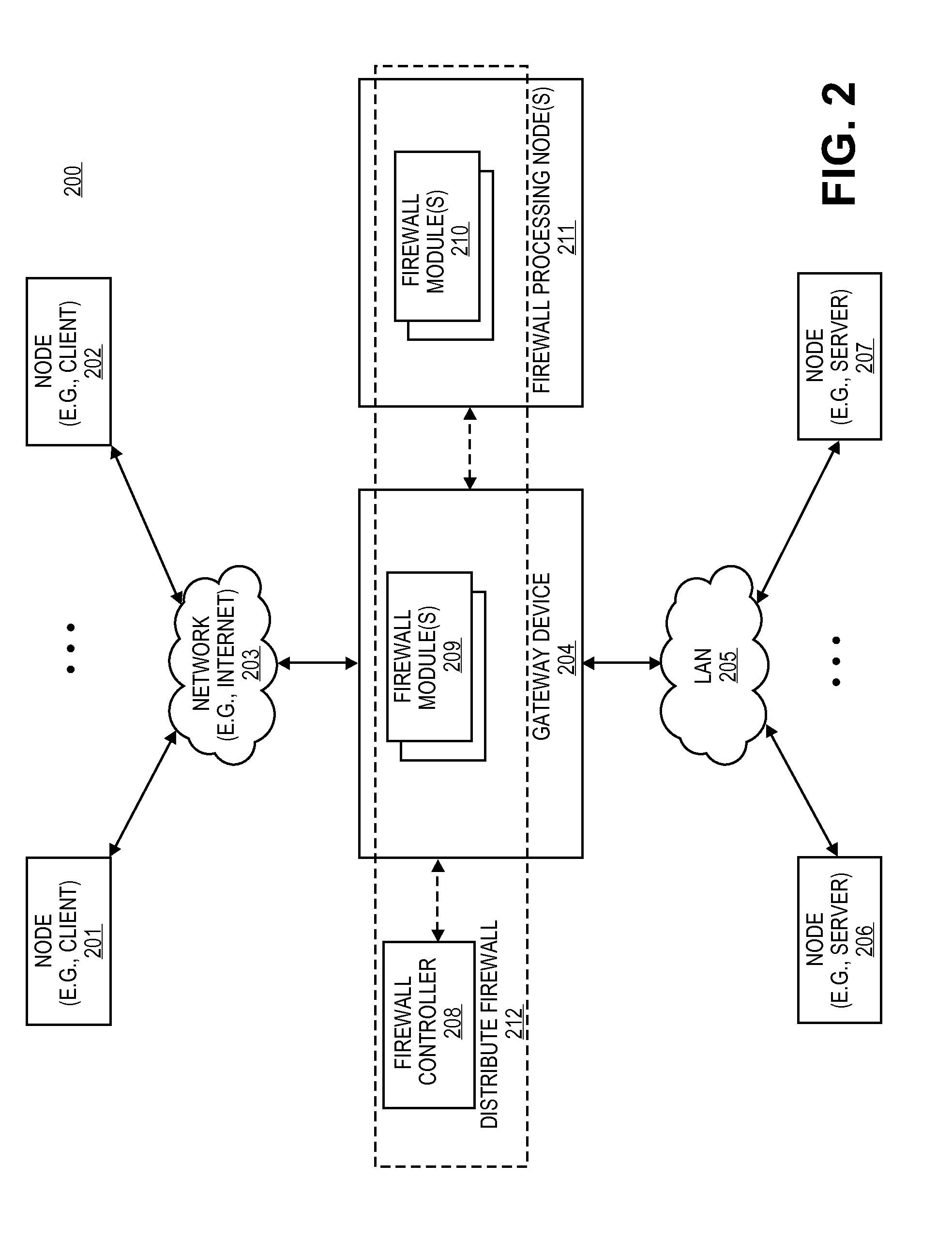
Distributed firewall architecture using virtual machines
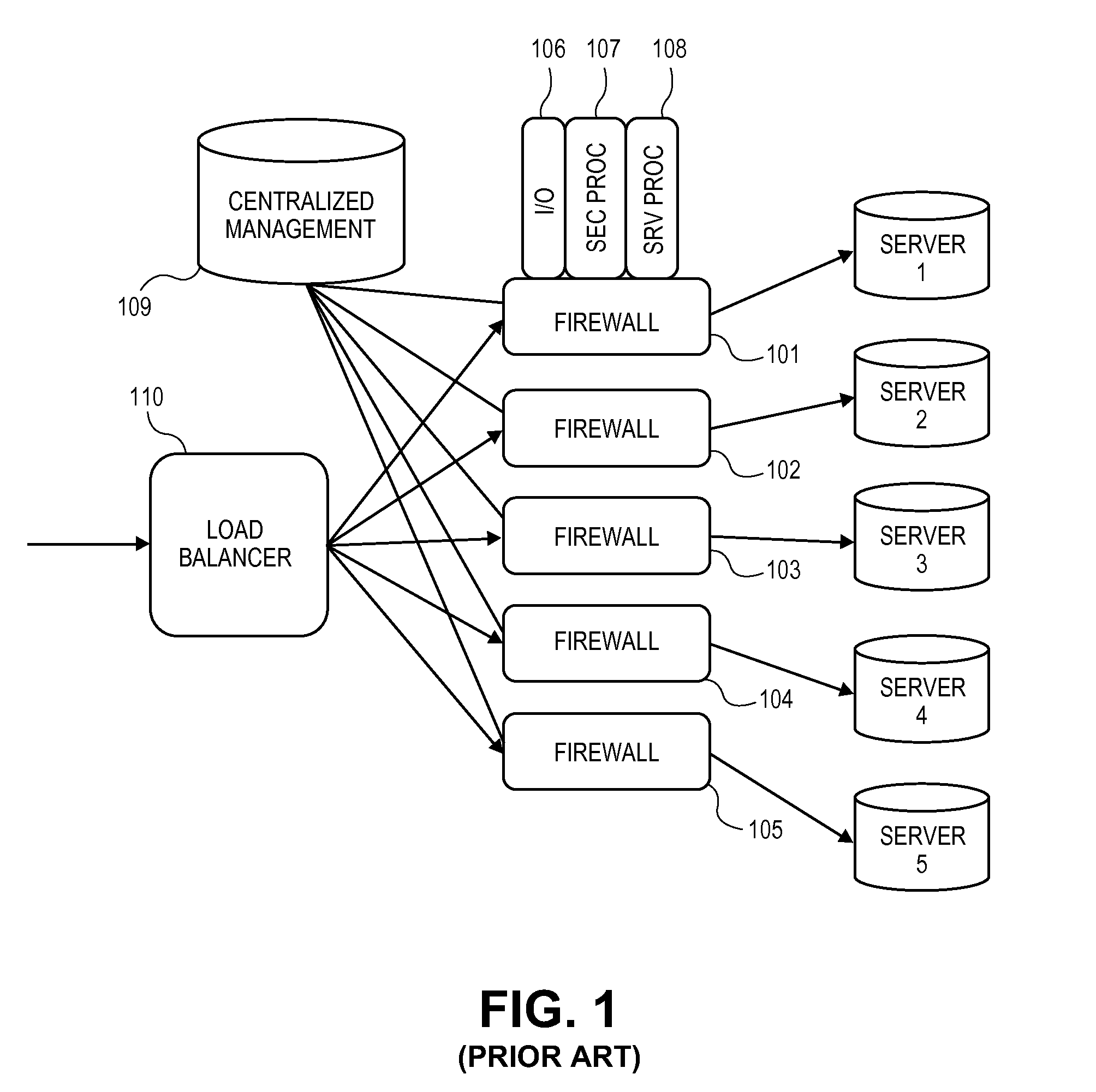
a virtual machine and firewall technology, applied in the field of network security, can solve the problems of not scaling well to protect networks, costing significant cpu and network resources, and separation of firewalls
- Summary
- Abstract
- Description
- Claims
- Application Information
AI Technical Summary
Benefits of technology
Problems solved by technology
Method used
Image

Examples
Embodiment Construction
[0017]Various embodiments and aspects of the inventions will be described with reference to details discussed below, and the accompanying drawings will illustrate the various embodiments. The following description and drawings are illustrative of the invention and are not to be construed as limiting the invention. Numerous specific details are described to provide a thorough understanding of various embodiments of the present invention. However, in certain instances, well-known or conventional details are not described in order to provide a concise discussion of embodiments of the present inventions.
[0018]Reference in the specification to “one embodiment” or “an embodiment” means that a particular feature, structure, or characteristic described in conjunction with the embodiment can be included in at least one embodiment of the invention. The appearances of the phrase “in one embodiment” in various places in the specification do not necessarily all refer to the same embodiment.
[0019...
PUM
 Abstract
Description
Claims
Application Information