
Rimless toilet with flush water distribution apparatus

a technology of water distribution apparatus and rimless toilet, which is applied in the field of toilets, can solve the problems of difficult inspection of parts of the underside of the rim, difficult to effectively clean around the rim, and often left uncleaned parts of the toilet for extended periods of time or indefinitely

Inactive Publication Date: 2012-08-23
IDEAL STANDARD INT
View PDF3 Cites 14 Cited by
  • Summary
  • Abstract
  • Description
  • Claims
  • Application Information

AI Technical Summary

Benefits of technology

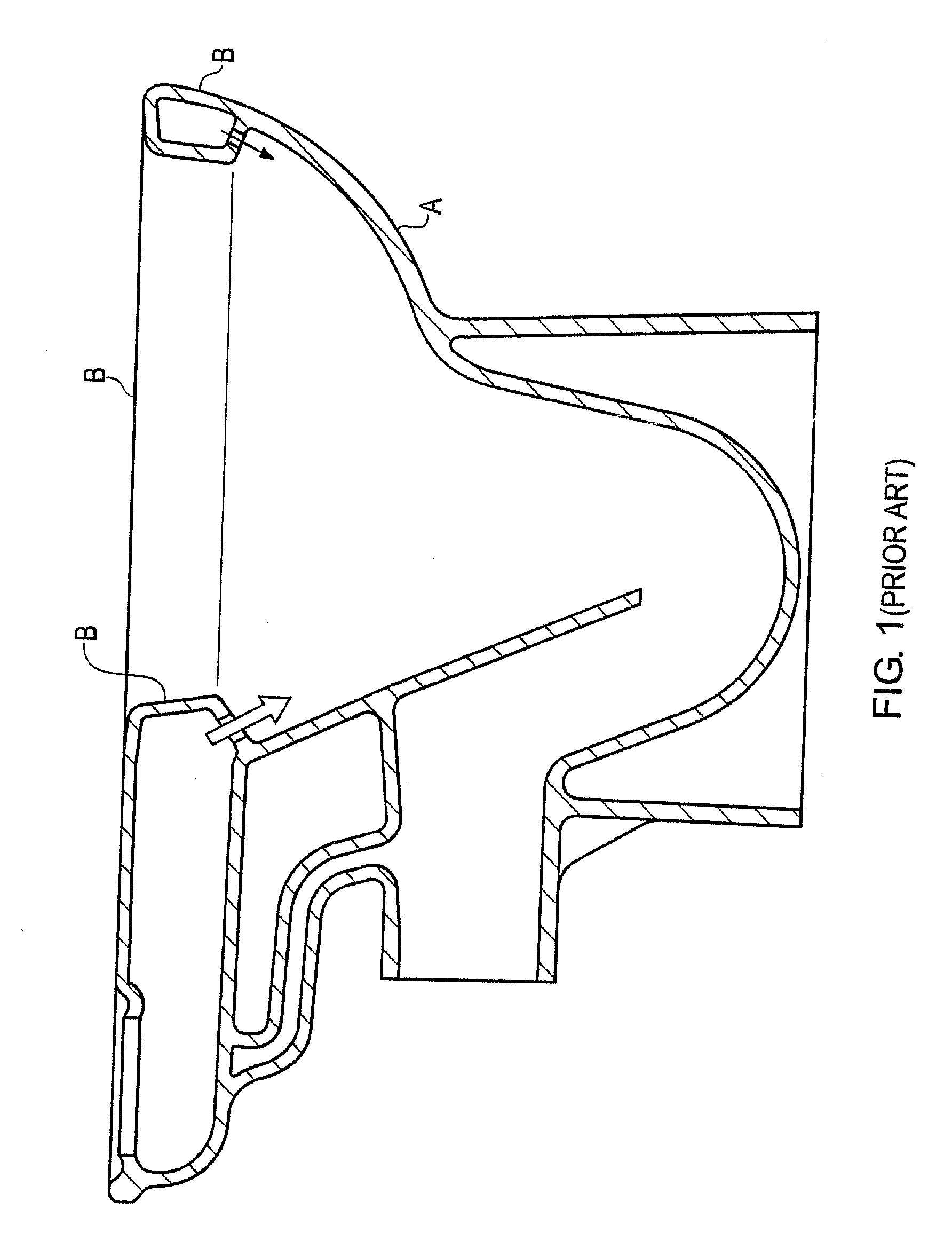
[0007]In accordance with the invention, substantially all of the flushing water received into the toilet is only directed in opposing and substantially horizontal directions by means of the two water inlets i.e. water is not directed from the inlet directly down and into the bowl as is the case in conventional toilets. In the prior art substantially all of the water received in the bowl is directed towards the U-bend to create the necessary flushing action as illustrated by the arrows in FIG. 1. Directing all of the water horizontally creates a flushing plume at an opposing side of the toilet bowl which cleans the inside surfaces of the toilet bowl and creates the necessary flushing plume. The use of a toilet without any kind of rim minimises the regions around the bowl at which germs, bacteria and matter may build-up and furthermore maximises the visibility of the inside of the bowl allowing easy and convenient inspection.
[0009]The term ‘rimless’ is intended to refer herein to a toilet bowl which is void of an overhanging surface extending around the upper surface of the rim. By removing the overhanging surface the visibility of the inside of the toilet bowl is substantially improved. In addition access to the bowl is improved for cleaning.
[0011]To maximise the flushing and cleaning action the flushing water may be introduced into the bowl close to the upper edge of the rimless bowl. Introducing the water at the top of the bowl maximises the area of the bowl over which the flushing water is arrange to flow and minimises the area of the bowl which is not cleaned.
[0015]In use water issues from the respective inlets and is directed along the top of the respective water guide and around the bowl. Each guide advantageously prevents the water from flowing in a manner as found in conventional toilets i.e. directly down towards the U-bend. In use the guides communicate water from the respective inlets and around the inner surface of the bowl so as to collide on the opposite side of the toilet bowl and to create a ‘plume’ of water which in turn flows into the U-bend. The arrangement of the guides advantageously provides a surface on which water may be communicated. In addition the guides are void of any concealed portions because there are no overhanging surfaces or rim and can be easily and conveniently inspected for cleanliness. As described above the guide surfaces are also advantageously convenient and easy to clean because they are readily accessible to a cleaner.
[0020]The guides or ledges may be provided with any suitable profile or configuration comprising a surface on which the water is supported and / or directed as it flows around the bowl. For example, the guides may be in the form of a substantially horizontal surface on which the water is supported and along which the water flows. As discussed above, such a surface advantageously supports the flow of water around the bowl and additionally allows for convenient inspection of the toilet (for cleanliness) and furthermore allows the toilet inner surface to be easily cleaned.
[0026]At the portion of each guide proximate the respective flushing water inlet the inlet may, as described above, be formed in a recess in the inner wall of the bowl. The recess is in effect formed of a lower surface defined by the tapered guide and an upper opposing surface which acts as a cover to prevent any spray passing from the respective water inlets over the top of the bowl as the water passes at its highest flow rate onto the guides. Advantageously this surface may taper into the wall of the bowl to maximise access and visibility of the inner surface of the bowl.

Problems solved by technology

Despite the popularity and advantages of conventional toilets there are a number of significant drawbacks with toilets incorporating a rim.
The profile of the rim can also make it difficult to effectively clean around the rim.
Furthermore, parts of the underside of the rim are difficult to inspect which means parts of the toilet are often left un-cleaned for extended periods of time or indefinitely.
However, the prior art designs fail to provide a toilet arrangement which offers an efficient and effective flushing action in combination with a toilet which substantially eliminates the possibility of germs and / or bacteria building up or being cultured in or around the rim.

Method used


Image

  • Rimless toilet with flush water distribution apparatus
  • Rimless toilet with flush water distribution apparatus
  • Rimless toilet with flush water distribution apparatus

Examples


Embodiment Construction

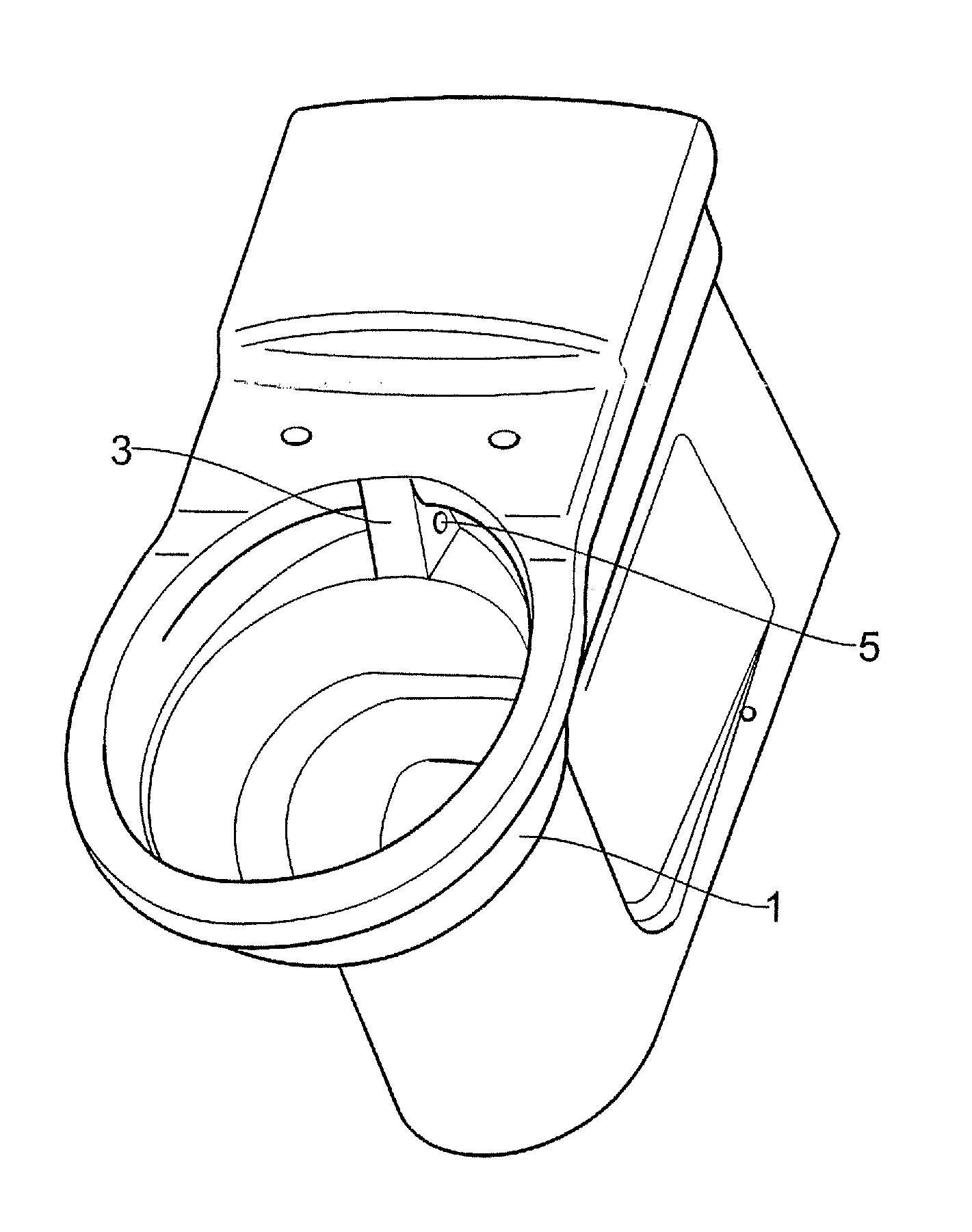
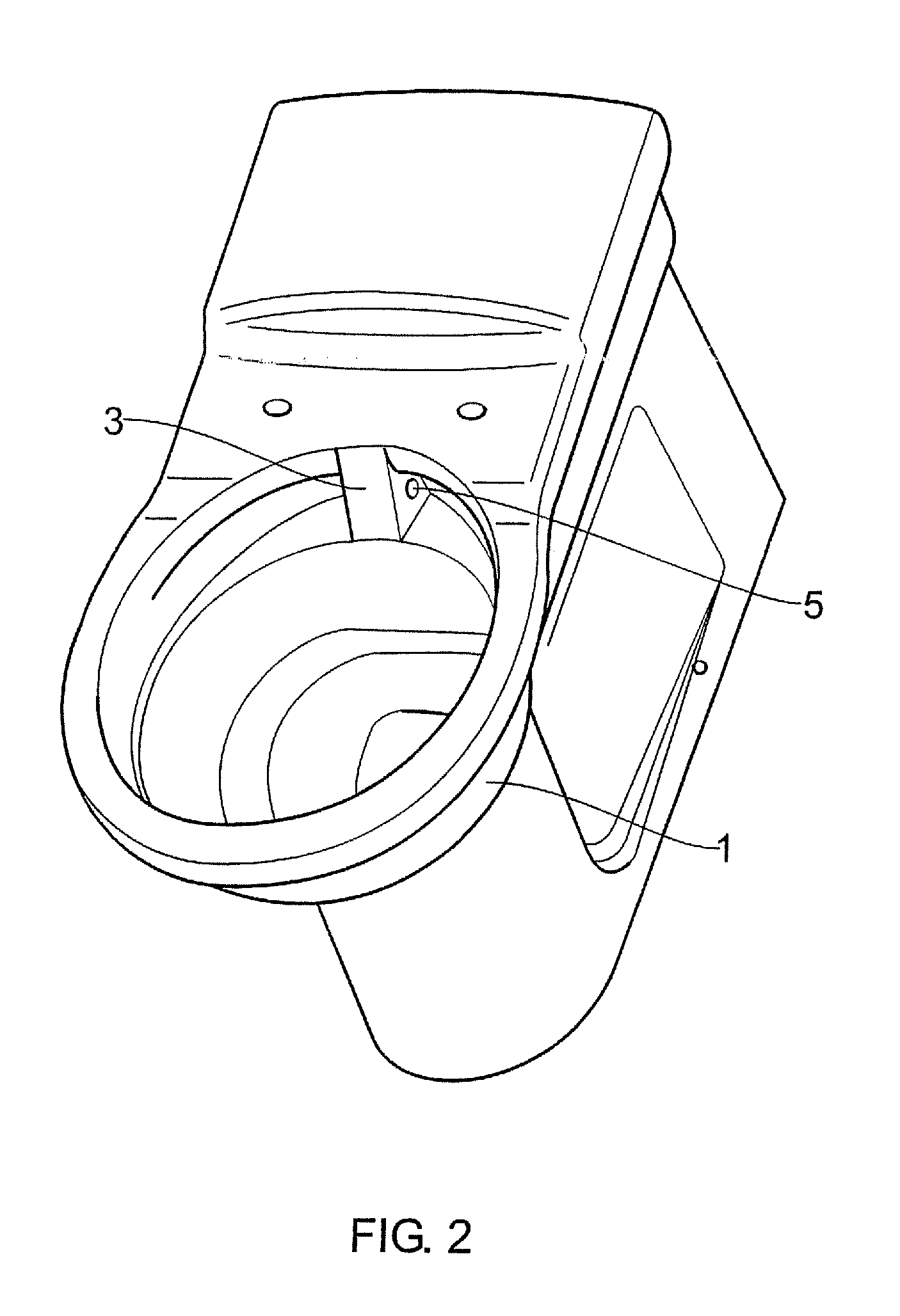
[0042]Referring to the drawings, the toilet according to the invention comprises a rimless toilet bowl 1 and a water reservoir (not shown) for supplying flushing water to said toilet bowl. As shown in FIGS. 2, 4 and 5 a water distribution apparatus or arrangement 3 is integrally formed with the inner wall of the toilet bowl 1. The distribution arrangement is discussed below in more detail with reference to FIGS. 7A and 8.

[0043]As shown in FIG. 4, the water distribution apparatus 3 includes a conduit 4 for receiving water to be supplied to the toilet bowl. This is in fluid communication with the water cistern (not shown). The distribution apparatus also includes two inlets to the toilet bowl 5 and 6 for supplying water to the toilet bowl from the conduit 4. The inlets may be any suitable size depending on the particular water pressures and characteristics of the system into which the toilet is installed. In one example the inlets are provided with a diameter of 20 mm with a tolerance...


PUM


Abstract

A toilet comprising a rimless toilet bowl and a water distribution apparatus arranged in use to communicate water in substantially horizontally opposing directions.

Description

CROSS REFERENCE TO RELATED APPLICATIONS[0001]This is a continuation of International Application No. PCT / GB2008 / 002986, with an international filing date of Sep. 3, 2008 which claims the benefit of Great Britain Patent Application Number 0717274.5 filed on Sep. 5, 2007, both of which are hereby incorporated by reference in their entirety.FIELD OF THE INVENTION[0002]The present invention relates to a toilet and specifically to a rimless toilet.BACKGROUND[0003]Various types of toilets have been available in the art for some time. An example of one conventional toilet is shown in FIG. 1, in cross-section. A conventional toilet typically comprises a toilet bowl or pan (reference A) and a toilet rim (reference B) extending around the top of the bowl. On flushing of the toilet water is directed from an inlet pipe into the back of the bowl. The majority of the water entering the toilet is directed in a generally vertical direction down the rear wall and towards the bottom of the bowl where...

Claims


Application Information

Patent Timeline
Patent Type & Authority Applications(United States)
IPC IPC(8): E03D11/00
CPCE03D2201/40E03D11/02
Inventor PEARSON, JOHN
Owner IDEAL STANDARD INT
Learn More