

Air-conditioning apparatus
- Summary
- Abstract
- Description
- Claims
- Application Information
AI Technical Summary
Benefits of technology
Problems solved by technology
Method used
Image

Examples
embodiment 1
[General Configuration of Air-Conditioning Apparatus 50]
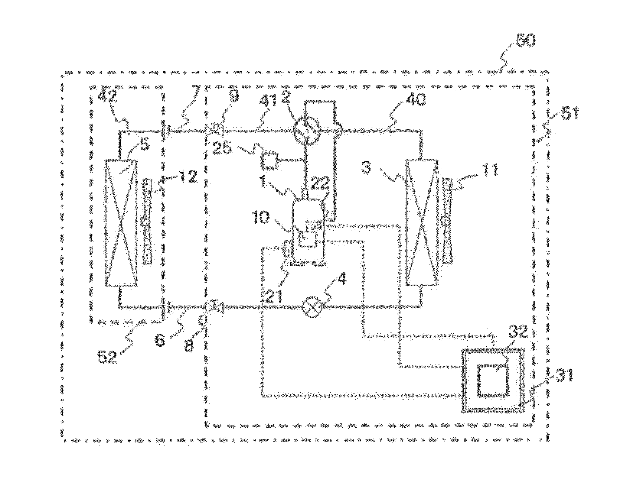
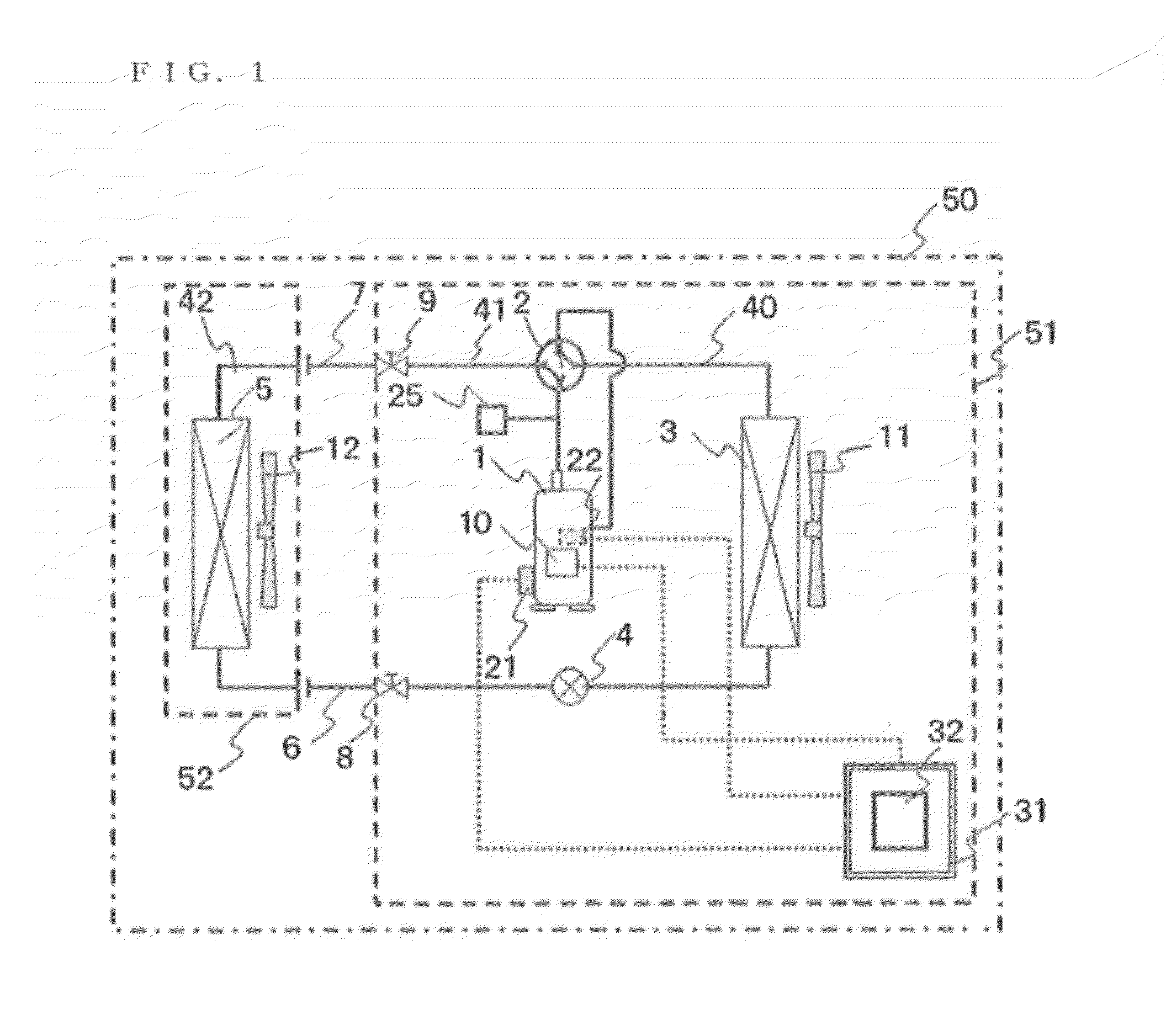
[0026]FIG. 1 is a general configuration diagram illustrating an air-conditioning apparatus 50 according to Embodiment of the invention.
[0027]As illustrated in FIG. 1, an air-conditioning apparatus 50 includes an outdoor unit 51, an indoor unit 52, and a refrigerant circuit 40 that is a circuit communicating the refrigerant circulating through the outdoor unit 51 and the indoor unit 52.
[0028]The refrigerant circuit 40 includes an outdoor refrigerant circuit 41 that is a heat source side refrigerant circuit provided with the outdoor unit 51, an indoor refrigerant circuit 42 that is a use side refrigerant circuit provided with the indoor unit 52, and a liquid side connecting piping 6 and a gas side connecting piping 7 that connects the outdoor refrigerant circuit 41 and the indoor refrigerant circuit 42.
[0029]The outdoor refrigerant circuit 41 includes at least a compressor 1, a four-way valve 2, an outdoor heat exchanger 3, an ex...
embodiment 2
[0065]In Embodiment 2, points that differ to the air-conditioning apparatus 50 according to Embodiment 1 will be described mainly.
[0066]The configuration of an air-conditioning apparatus 50 of Embodiment 2 is the same as the configuration of the air-conditioning apparatus 50 of Embodiment 1.
[Time-Dependent Change of Quantity of State While Compressor 1 is Undergoing Heating Operation]
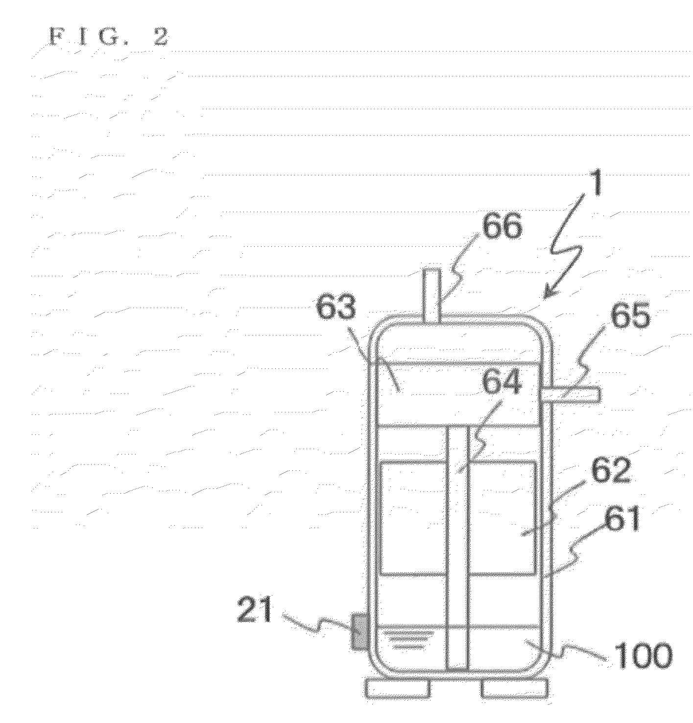
[0067]FIG. 6 is a diagram showing time-dependent changes in the temperature of a compressor 1, a liquid refrigerant amount in the compressor 1, and the viscosity of a lubricant oil 100, while the compressor 1, according to the air-conditioning apparatus 50 of Embodiment 2, is not in operation.
[0068]As illustrated in FIG. 6, when a controller 31 makes a compressor heating unit 10 heat the compressor 1, the liquid refrigerant that has dissolved into the lubricant oil 100 in the compressor 1 is gasified and is reduced. Then, due to the gasification of the liquid refrigerant, the concentration of the lubric...
PUM
 Abstract
Description
Claims
Application Information