Gas Carrying Threading Device of Sewing Machine

a threading device and sewing machine technology, applied in the direction of sewing apparatus, take-up devices, textiles and paper, etc., can solve the problems of forced hardship, troublesome manual work of the operator, insufficient performance, etc., and achieve the effect of convenient operation and easy handling

Active Publication Date: 2012-08-23
SUZUKI MFG CO LTD
View PDF4 Cites 36 Cited by
  • Summary
  • Abstract
  • Description
  • Claims
  • Application Information

AI Technical Summary

Benefits of technology

[0028]According to the gas carrying threading device of sewing machine of the present invention, in the insertion operation of the looper thread to the looper, when inserting the looper thread from the thread introducing part, the thread introduction of the looper thread can be performed certainly by the looper thread introduction mechanism.
[0029]Besides, according to the gas carrying threading device of sewing machine of the present invention, the pressurized gas for the gas carrying of the looper thread is produced by a gas supply pump which is operated by the sewing machine motor, and the threading to the looper can be performed by one-touch operation.
[0030]Further, according to the gas carrying threading device of sewing machine of the present invention, the looper threading changeover operation can be performed in one hand by the looper threading/stitch forming changeover mechanism.
[0031]Therefore, according to the gas carrying threading device of sewing machine of the present invention, by connecting with the hollow thread guide which leads from the thread outlet of the loop-taker point o

Problems solved by technology

However in the structure of such the gas carrying threading, in the case of threading operation, when inserting the looper thread from the thread introduction portion, it is insufficient to perform certainly the thread introduction of the looper thread for an operator who is not accustomed for the gas carrying threading.
Besides, in the structure of such the gas carrying threading, because a means for generating the pressurized gas for performing the gas carry

Method used


Image

  • Gas Carrying Threading Device of Sewing Machine
  • Gas Carrying Threading Device of Sewing Machine
  • Gas Carrying Threading Device of Sewing Machine

Examples


Embodiment Construction

[0056]Hereinafter the preferable embodiment that the gas carrying threading device of sewing machine of the present invention is applied to the three-needle / six-thread serger (double chain stitch sewing machine) is explained in detail by referring to the views.

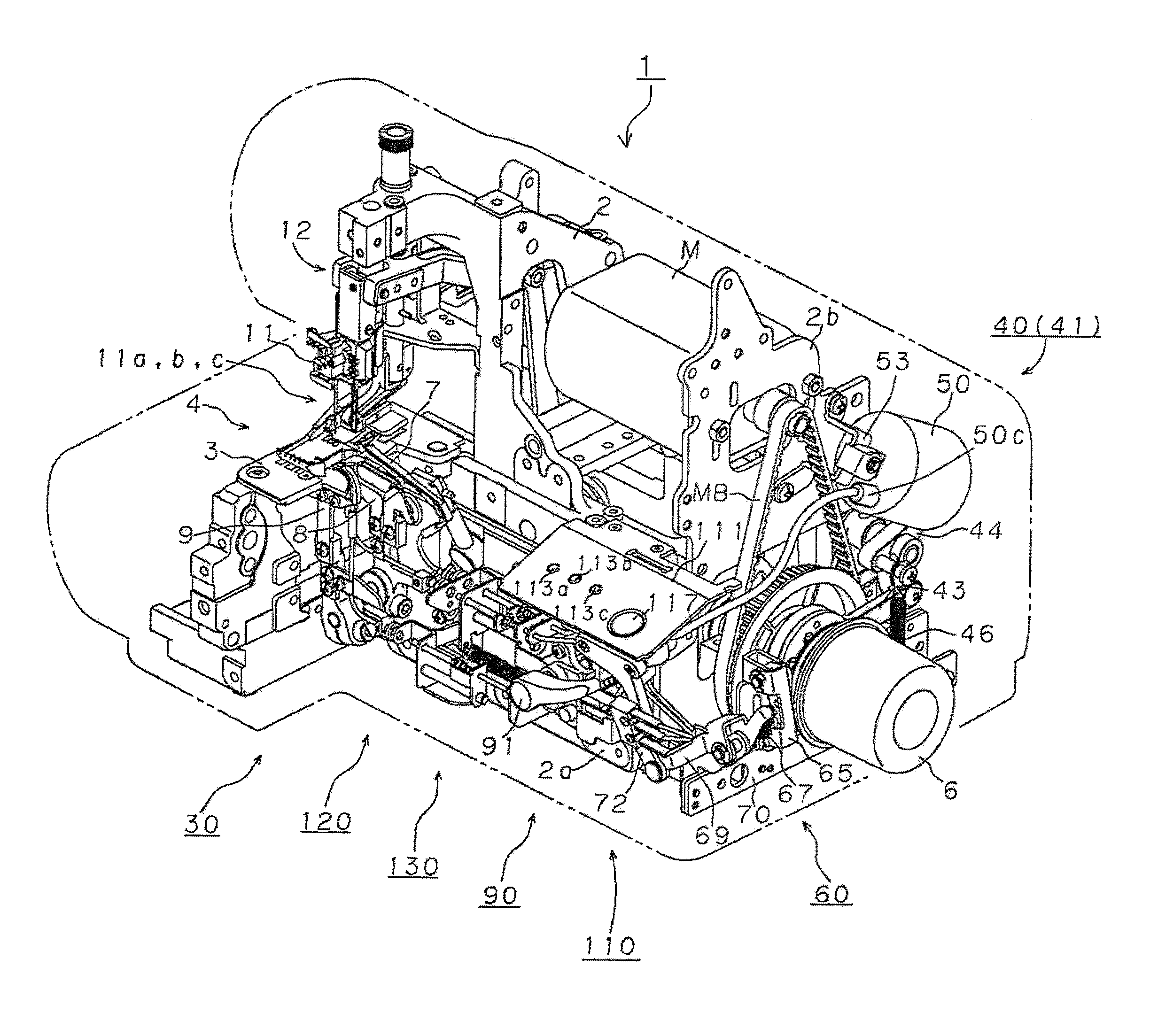
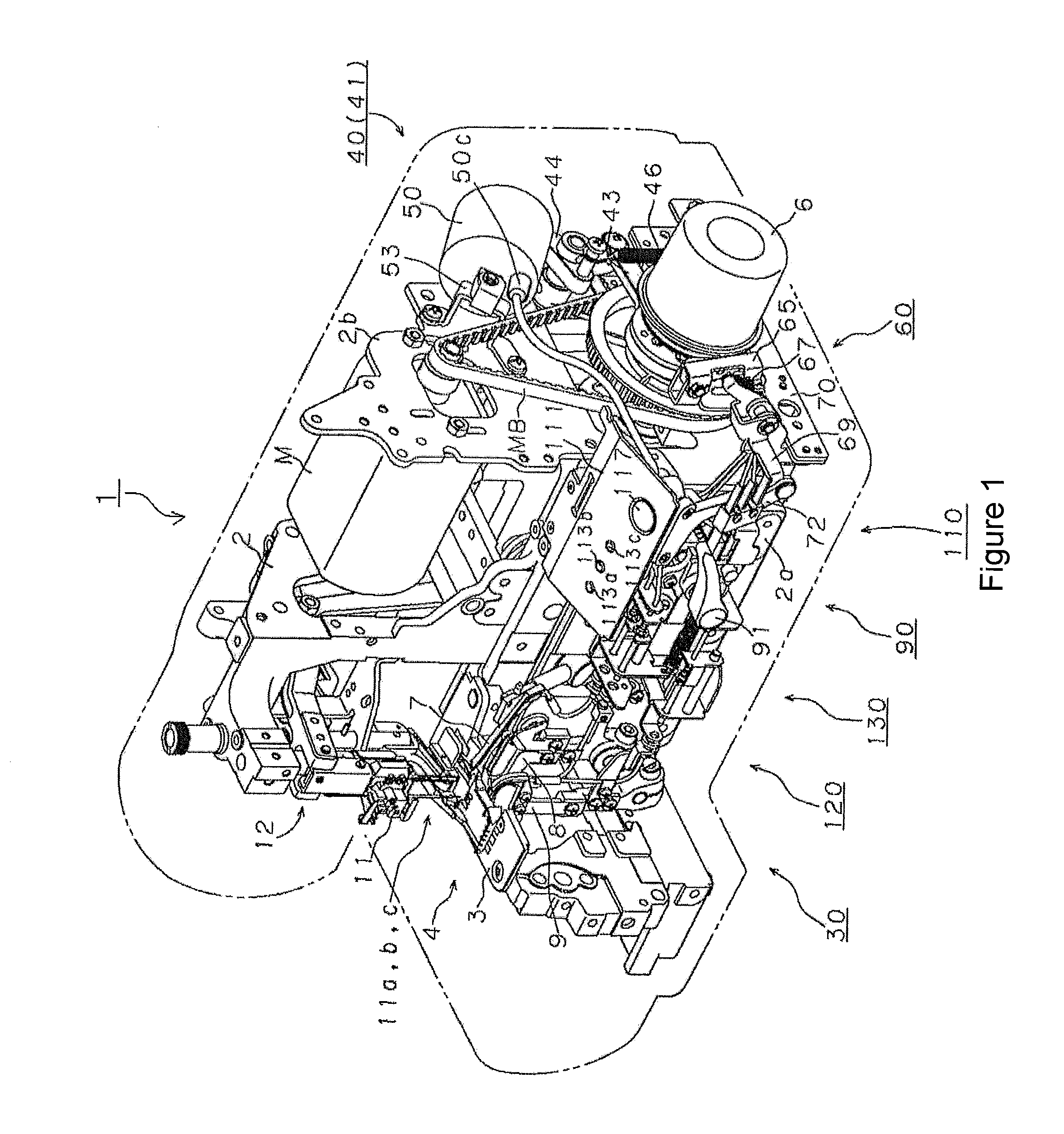
[0057]As shown in FIG. 1, this serger 1 is composed from a main frame 2 which forms a bed and an arm. The main frame 2 has a sub-frame 2a and a sub-frame 2b.

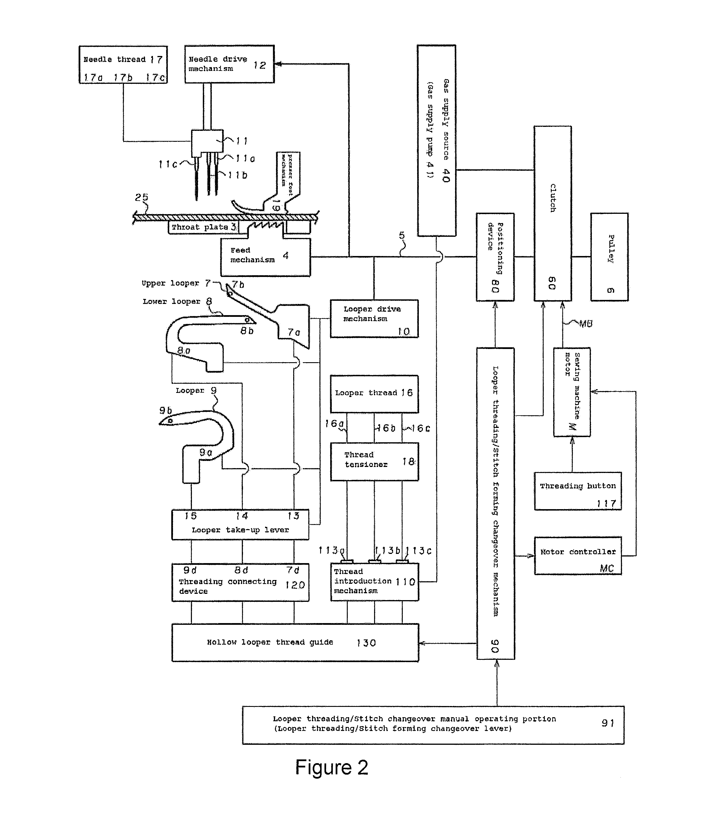
[0058]The sewing machine motor M is attached to the sub-frame 2b, and a drive shaft 5 lengthens along the frame 2 in a horizontal direction (FIG. 2, FIG. 7-FIG. 9, FIG. 12-FIG. 13). As described below, the drive shaft 5 is rotated and driven through a clutch 60 by using a timing belt MB by the sewing machine motor M.

[0059]As shown in FIG. 1 and FIG. 2, a stitch forming device 30 is formed by needle 11a, 11b, 11c which perform vertical motion by being fixed at a needle clamp 11 which performs the vertical motion in synchronization with the drive shaft 5 and piercing a thro...


PUM


Abstract

Pressurized gas for carrying looper thread by gas is generated by gas supply pump operated by changing over a sewing-machine motor, which drives stitch forming device, looper threading is performed through loopers by one-touch operation. Gas carrying threading device of sewing machine, comprising: looper thread introduction mechanism inserts looper thread guided to loopers; hollow looper thread guide extends from looper thread introduction mechanism to looper thread inlets and has looper thread guide outlets; gas supply pump for performing looper threading by carrying looper thread by gas from looper thread introduction area through hollow looper thread guide to looper thread loop-taker point outlets; clutch for transmitting power from sewing machine motor M to drive shaft which drives stitch forming device including loopers at time of stitch formation or to gas supply pump at time of looper threading.

Description

FIELD OF THE ART[0001]The present invention relates to a gas carrying threading device of sewing machine, particularly relates to the gas carrying threading device of sewing machine such as a serger, a double chain stitch sewing machine, or a interlock stitch sewing machine for performing a threading automatically to a looper by utilizing a pressurized gas.BACKGROUND OF THE ART[0002]Heretofore, in such as the serger, the double chain stitch sewing machine, or the interlock stitch sewing machine, the gas carrying threading device which is connected by a hollow looper thread guide which leads from a thread introduction portion which inserts the looper thread to a looper thread guide outlet of a loop-taker point of the looper and which feeds a looper thread by utilizing a flow of a pressurized gas which is supplied to the hollow looper thread guide is known. Herewith, a complicated thread guard is unnecessary and a threading that a handleability is easy can be performed. Therefore, the...

Claims


Application Information

Patent Timeline
IPC IPC(8): D05B57/02D05B51/00D05B57/32
CPCD05B87/00D05B87/02D05B57/02D05D2207/04D05B63/00D05B63/04
Inventor SAKUMA, KOUICHIISHIKAWA, MASATO
Owner SUZUKI MFG CO LTD
Why Eureka
Try Eureka