Water meter mounting bracket system and method

a technology for mounting brackets and water meters, applied in the direction of volume flow measuring devices, rigid containers, light support devices, etc., can solve the problems of rf transmitters floating off or otherwise becoming detached from the pipe, affecting the installation efficiency of conventional methods, so as to prevent the vertical displacement of the water-meter device

Active Publication Date: 2012-08-23
RINALDI DAVID C +1
View PDF9 Cites 8 Cited by
  • Summary
  • Abstract
  • Description
  • Claims
  • Application Information

AI Technical Summary

Benefits of technology

[0016]The aforementioned aspects may be achieved in another aspect of the present inventive concept by providing a method of manufacturing a water meter mounting bracket system. The method may include the step of forming a frame having an abutment surface operable to engage a surface of a water-meter enclosure having a lid. The method may further include the step forming an interior component that depends from the frame and / or at least partially spans the void. The interior component may have at least one receiver operable to (i) position a water-meter device within the water-meter enclosure, and / or (ii) prevent vertical displacement of the water-meter device when the lid is fitted to the water-meter enclosure.
[0017]The abutment surface of the frame may be annular with an engagement surface that corresponds to and is operable to be received by, in its entirety, a portion of a water meter enclosure so that the frame is provided with uniform support when trapped between the surface of the water-meter enclosure and the lid of the water-meter enclosure. The interior component may include a vertical sidewall portion having an abutment surface operable to face a portion of the water-meter enclosure and prevent horizontal displacement of the frame relative to the water-meter enclosure when the lid is fitted to the water-meter enclosure. The at least one receiver of the interior component may be provided through a horizontal receiver portion of the interior component that extends perpendicular from the vertical sidewall portion of the interior component.
[0018]The aforementioned aspects may be achieved in another aspect of the present inventive concept by providing a method of mounting a component of a water meter to a bracket system. The method may include the step of securing a frame to a water-meter enclosure having a lid. The frame may have a planar void on an interior thereof and opposing abutment surfaces operable to engage surfaces of the water-meter enclosure and the lid. The method may further include the step of securing a water-meter device to an interior component that depends from the frame and / or at least partially spans the void. The interior component may have at least one receiver operable to (i) position the water-meter device within the water-meter enclosure, and / or (ii) prevent vertical displacement of the water-meter device when the lid is fitted to the water-meter enclosure.
[0019]The abutment surface of the frame may be annular and operable to provide uniform support to the frame when trapped between the water-meter enclosure and the lid. The interior component may include a vertical sidewall portion having an abutment surface operable to face a portion of the water-meter enclosure and prevent horizontal displacement of the frame relative to the water-meter enclosure when the lid is fitted to the water-meter enclosure. The at least one receiver of the interior component may be provided through a horizontal receiver portion of the interior component that extends perpendicular from the vertical sidewall portion of the interior component. The water-meter device may be secured to the at least one receiver of the interior component via a mounting assembly.

Problems solved by technology

While some RF transmitters may be installed through the enclosure's lid, such are subject to the aforementioned damage.
Such convention methods are problematic because subsurface enclosures occasionally fill with water, which may cause the RF transmitter to float off or otherwise become detached from the pipe.
Additionally, such conventional methods are difficult to install because subsurface enclosures do not have a uniform depth.
Presently, there are no readily-available systems for securely positioning water-usage monitoring equipment in a subsurface enclosure.

Method used


Image

  • Water meter mounting bracket system and method
  • Water meter mounting bracket system and method
  • Water meter mounting bracket system and method

Examples


Embodiment Construction

[0030]The present inventive concept is susceptible of embodiment in many forms. While the drawings illustrate, and the specification describes, certain embodiments of the invention, it is to be understood that such disclosure is by way of example only. The principles of the present inventive concept are not limited to the particular disclosed embodiments.

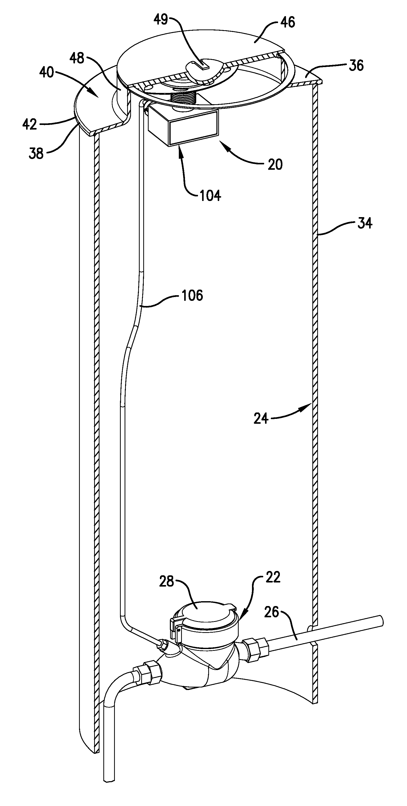
[0031]With initial reference to FIG. 1, a water meter mounting bracket system 20 is generally illustrated in an exemplary embodiment in use a water meter 22 that is installed in a water meter enclosure 24. The water meter 22 is installed along a length of a water pipe 26. The water meter 22 has a cap 28 that conceals a meter display operable to monitor a volume of water passing through the water meter 22, that is, water consumed by an end user via the water pipe 26. The water meter enclosure 24 has a below ground portion 34 that extends into the ground and an above ground portion 36 of the water meter enclosure 24 that extends to de...


PUM

PropertyMeasurementUnit
vertical displacementaaaaaaaaaa
perimeteraaaaaaaaaa
radiusaaaaaaaaaa

Abstract

A bracket system and method to retrofit a subsurface water meter enclosure with a mount so as to provide secure positioning means suitable for components related to a water meter such as water-usage monitoring equipment. The system is only removable from the water meter enclosure via disassembling the water meter enclosure.

Description

CROSS-REFERENCE TO RELATED APPLICATION[0001]This patent application claims priority to U.S. Provisional Patent Application No. 61 / 445,354 filed on Feb. 22, 2011 and titled MOUNTING BRACKET FOR A REMOTE-READ WATER METER RF TRANSMITTER UNIT, the entire contents of which is herein incorporated by reference in its entirety.BACKGROUND[0002]1. Field of the Invention[0003]The present inventive concept generally relates to mounting systems for equipment related to utility meters. More specifically, embodiments of the present inventive concept concern a bracket system and method being particularly suitable for retrofitting a subsurface water meter enclosure with a mount so as to provide secure positioning means suitable for components related to a water meter housed in the water meter enclosure such as water-usage monitoring equipment.[0004]2. Description of the Related Art[0005]Residential and commercial consumers subscribe to various utilities, e.g., electricity, water, and gas, which are ...

Claims


Application Information

Patent Timeline
Patent Type & Authority Applications(United States)
IPC IPC(8): F16M13/02B23P19/00B23P17/04
CPCG01F15/063G01F15/065Y10T29/49Y10T29/49826G01F15/18
Inventor RINALDI, DAVID C.AMREIN, JOHN T.
Owner RINALDI DAVID C
Why Eureka
Try Eureka