Structure of seat back with headrest

a seat back and headrest technology, applied in the direction of vehicle components, pedestrian/occupant safety arrangements, vehicle arrangements, etc., can solve the problems of seat occupants feeling a hard objectionable touch at the back portion of their seat, high cost, and cushioning degr

Active Publication Date: 2012-08-23
TACHI S CO LTD
View PDF2 Cites 15 Cited by
  • Summary
  • Abstract
  • Description
  • Claims
  • Application Information

AI Technical Summary

Benefits of technology

[0009]In view of the above-stated drawbacks, it is a purpose of the present invention to provide an improved structure of seat back in combination with a headrest unmovable forwardly and backwardly of the seat back, which is of a simplified structure wherein a resilient support element for supporting a seat occupant's back portion can be displaced backwardly and upwardly by an excessive great load applied thereto in the case of rear-end collision, to thereby quickly bring a head of the seat occupant to a point close to the headrest, prior to the head being directly pressed against the headrest.
[0017]wherein, in case of rear-end collision, upon receiving an excessive great load applied via the seat back padding from the seat occupant who is pressed backwardly under inertia against the seat back, the resilient support element is forcibly displaced far backwardly from the normal support position, together with the back portion of the seat occupant, which overcomes the biasing force of the biasing element, thereby causing the biasing element to resiliently stretch to permit the upper end portion of the resilient support element to be displaced backwardly and upwardly, via the movable connecting element, with respect to the seat back frame, so that a head of the seat occupant is brought to a point close to the headrest, thereby reducing the certain distance between the head and the headrest, prior to the head of the seat occupant being directly pressed against the headrest.

Problems solved by technology

However, the above-described prior-art arrangement of seat back and active headrest has been with the problem that the seat back structure thereof is very complicated with, many mechanisms incorporated therein, hence requiring troublesome and time-consuming processes for assembling the seat back, with highly increasing costs involved, and that the provision of the pressure receiving element not only limits a cushioning degree of the seat back, which does not provide a deep resilient support touch to a seat occupant's back portion, but also makes the seat occupant feel a hard objectionable touch at his or her back portion.

Method used


Image

  • Structure of seat back with headrest
  • Structure of seat back with headrest
  • Structure of seat back with headrest

Examples


Embodiment Construction

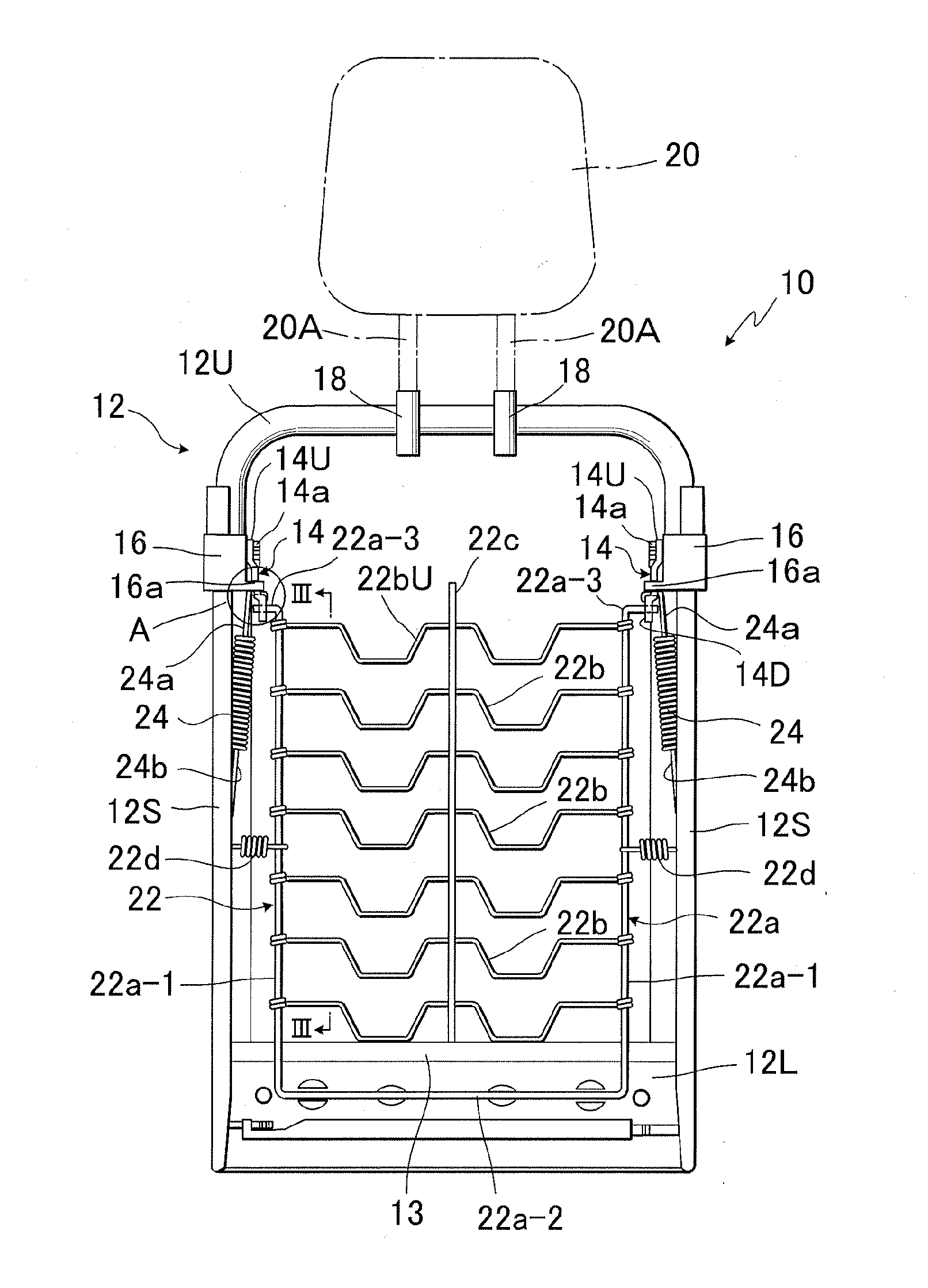
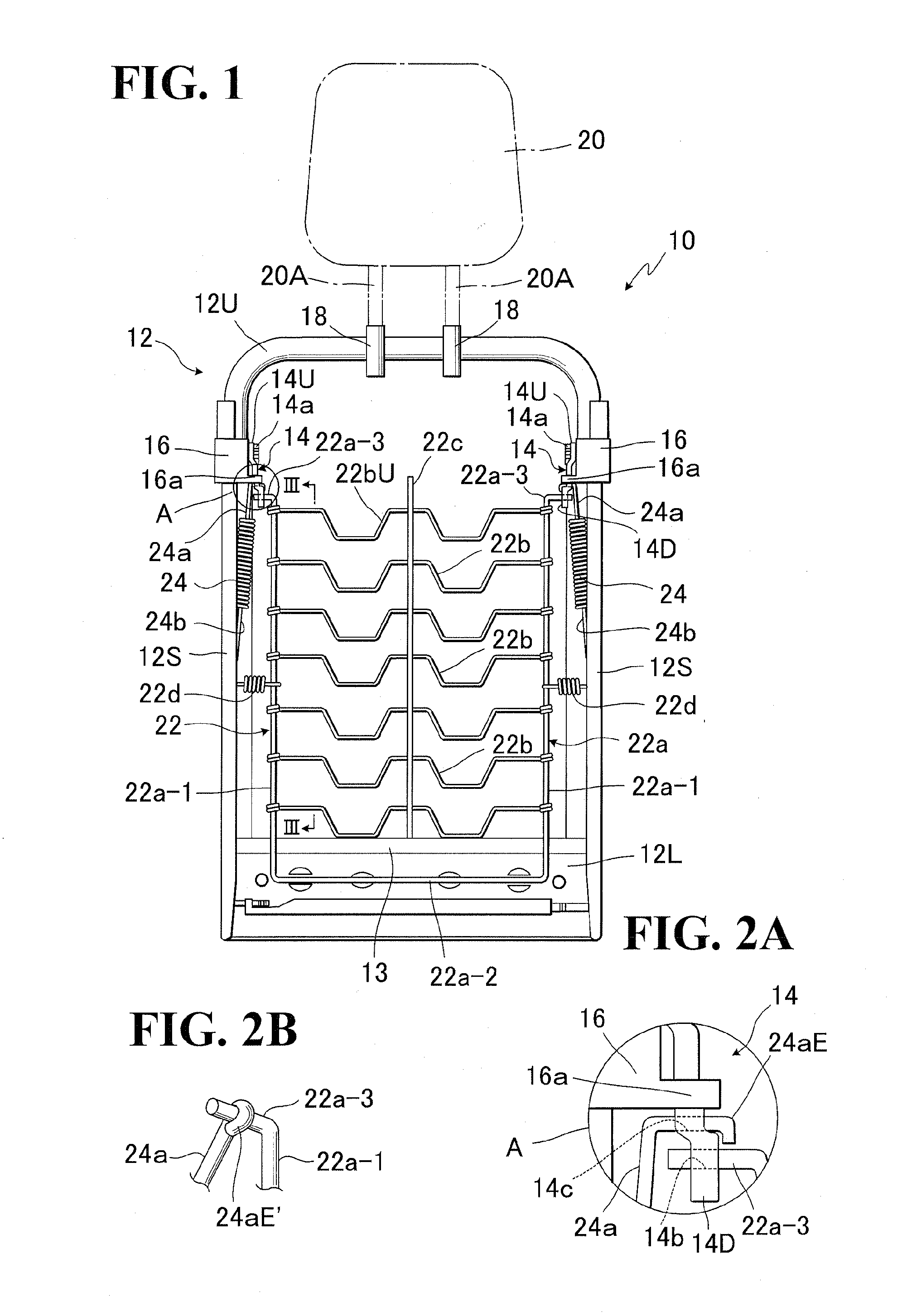
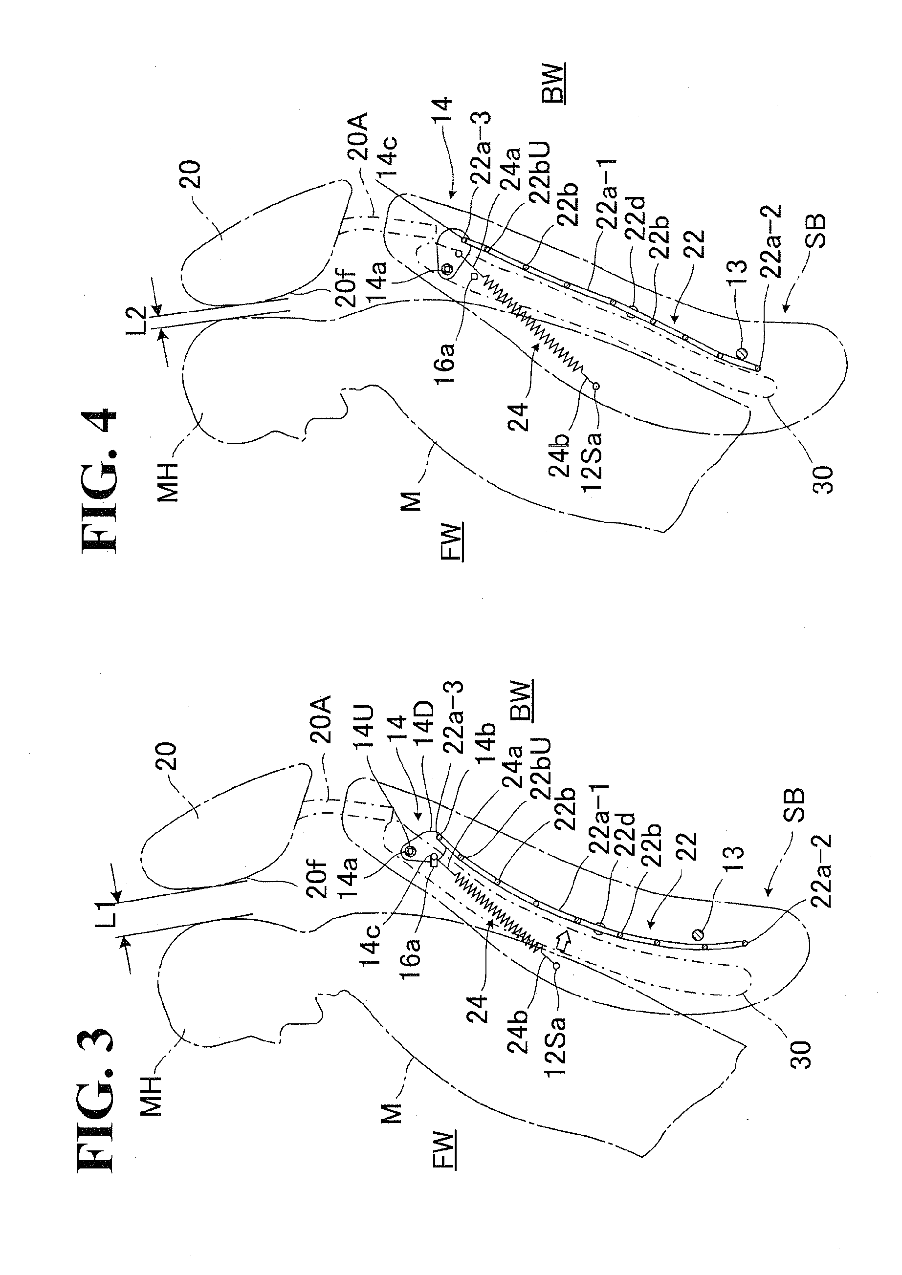
[0031]Referring to FIGS. 1 to 4, there is illustrated one preferred embodiment of seat back structure generally designated by (10) in accordance with the present invention, which is provided with a headrest (20). Designation (SB) denotes a seat back of vehicle seat which has such seat back structure (10) therein and covered with an upholstery including a trim cover assembly (not shown) and a foam padding (30).

[0032]It is to be noted that the wording “forward” or “forwardly” refers to a forward side (FW) facing forwardly of the seat (S), whereas the wording “backward” or “backwardly” refers to a backward side (BW) facing backwardly of the seat (S).

[0033]As shown in FIG. 1, a seat back frame (12) to be provided in the seat back (SB) is of a substantially rectangular configuration which is formed by: an upper frame member (12U); a pair of lateral frame members (12S) (12S); and a lower frame member (12L).

[0034]Designation (13) denotes a known auxiliary cross bar member which is extended...


PUM


Abstract

A seat back of vehicle seat, on which a headrest unmovable in fore-and-aft direction is mounted, is constructed such that a resilient support member for supporting a back portion of seat occupant is provided therein, and the upper region of that resilient support member is operatively connected, via movable connecting element, with a basing element. When a rear-end collision occurs, the resilient support member is displaced far backwardly by excessive great load applied thereto from the seat occupant, overcoming a biasing force of the biasing element, thereby causing the basing element to stretch long, so that the resilient support member with the seat occupant's back portion thereon is displaced backwardly and upwardly under guidance of the movable connecting element so as to quickly bring a head of the seat occupant to a point close to the headrest, prior to the head being directly pressed against the headrest.

Description

BACKGROUND OF THE INVENTION[0001]1. Field of the Invention[0002]The present invention relates to a seat back structure of vehicle seat provided with a headrest. In particular, the invention is directed to a seat back structure of vehicle seat so designed that, when a rear-end collision occurs, a seat occupants head is brought to a point adjacent to a headrest mounted on the seat back, so that the head is quickly received by the headrest with a minimum impact, to thereby protect a neck of the seat occupant against damage, such as a whiplash injury.[0003]2. Description of Prior Art[0004]For example, the Japanese Laid-Open Patent Publication No. 2007-186103 (JP 2007-186103 A) and the U.S. Pat. No. 7,540,562 disclose a seat back structure with a movable headrest, which is designed for protecting a seat occupant's head against damage in the case of a rear-end collision. In brief, when a rear-end collision occurs, the body of seat occupant is naturally displaced backwardly of the seat und...

Claims


Application Information

Patent Timeline
Patent Type & Authority Applications(United States)
IPC IPC(8): B60N2/427B60N2/42
CPCB60N2/4228B60N2/7094B60N2/4885B60N2/888
Inventor KANDA, KENJI
Owner TACHI S CO LTD
Why Eureka
Try Eureka