Image capturing device, adjusting device, and optical axis adjusting system for image capturing device

a technology of image capturing and optical axis, which is applied in the direction of closed circuit television system, color television details, television systems, etc., can solve the problems of inability to obtain desired images, misalignment of optical axis direction with respect to the traveling direction, etc., and achieve accurate adjustment, halation, and accurate adjustment

Inactive Publication Date: 2012-08-23
TOYOTA JIDOSHA KK
View PDF5 Cites 15 Cited by
  • Summary
  • Abstract
  • Description
  • Claims
  • Application Information

AI Technical Summary

Benefits of technology

[0018]With the first aspect of the present invention, the optical axis of the image capturing device can be adjusted accurately. Specifically, when adjusting the optical axis of the image capturing device, the setting parameter for image-capturing is fixed to an adjustment setting value. Therefore, the setting parameter for image-capturing will not be changed in accordance with the brightness of the surrounding environment, and thereby, will not be influenced by the surrounding environment. As a result, for example, an image of an object that is used as a standard target for an optical axis adjustment can be captured clearly. Consequently, the optical axis can be adjusted accurately based on the image that has been captured clearly
[0019]With the second aspect of the present invention, the adjustment setting value can be changed as appropriate to an arbitrary value set by the user. For example, one envisioned situation is a case where multiple image capturing devices are continuously or simultaneously adjusted at a manufacturing plant or the like. In this case, the multiple image capturing devices each can acquire adjustment setting values from the identical adjusting device. Therefore, when the user once changes the adjustment setting value by using the adjusting device, the adjustment setting values used by each of the image capturing devices at the time of adjusting can be changed all at once. As a result, the user can change the adjustment setting values used by each of the multiple image capturing devices at the time of adjusting, with a small number of operation steps.
[0020]With the third aspect of the present invention, the user can confirm the brightness (image brightness) of the image captured at the time of the optical axis adjustment. Therefore, the user can change the setting parameter for image-capturing in accordance with the image brightness. For example, when the image brightness is relatively high and when it is thought that halation can easily occur, the user can change the adjustment setting value so as to lower the brightness of the captured image.
[0021]With the fourth aspect of the present invention, the image brightness can be calculated using a simple process.
[0022]With the fifth aspect of the present invention, the brightness of the target in the captured image is displayed as the image brightness. Therefore, the user can confirm a numerical value of the image brightness and then can determine whether or not the brightness of the target in the captured image is at an easily recognizable level.
[0023]With the sixth aspect of the present invention, the exposure time of the image capturing device can be set to be the adjustment setting value at the time of the optical axis adjustment. As a result, at the time of the optical axis adjustment, the brightness of the image captured by the image capturing device can be arbitrarily and easily adjusted.

Problems solved by technology

When attaching such a camera to a vehicle, misalignment of an optical axis direction occurs with respect to the traveling direction of the vehicle when attaching the camera due to mechanical factors and control-technological factors.
A misalignment in the optical axis direction of the camera can lead to cases where a desired image cannot be obtained due to shifting in focus or not being able to capture a desired range for image-capturing.

Method used


Image

  • Image capturing device, adjusting device, and optical axis adjusting system for image capturing device
  • Image capturing device, adjusting device, and optical axis adjusting system for image capturing device
  • Image capturing device, adjusting device, and optical axis adjusting system for image capturing device

Examples


first embodiment

[0036

[0037]Descriptions are provided in the following with reference to FIG. 1 to FIG. 6 for an image capturing device 10 and an optical axis adjusting system 1 of the image capturing device according to the first embodiment of the present invention.

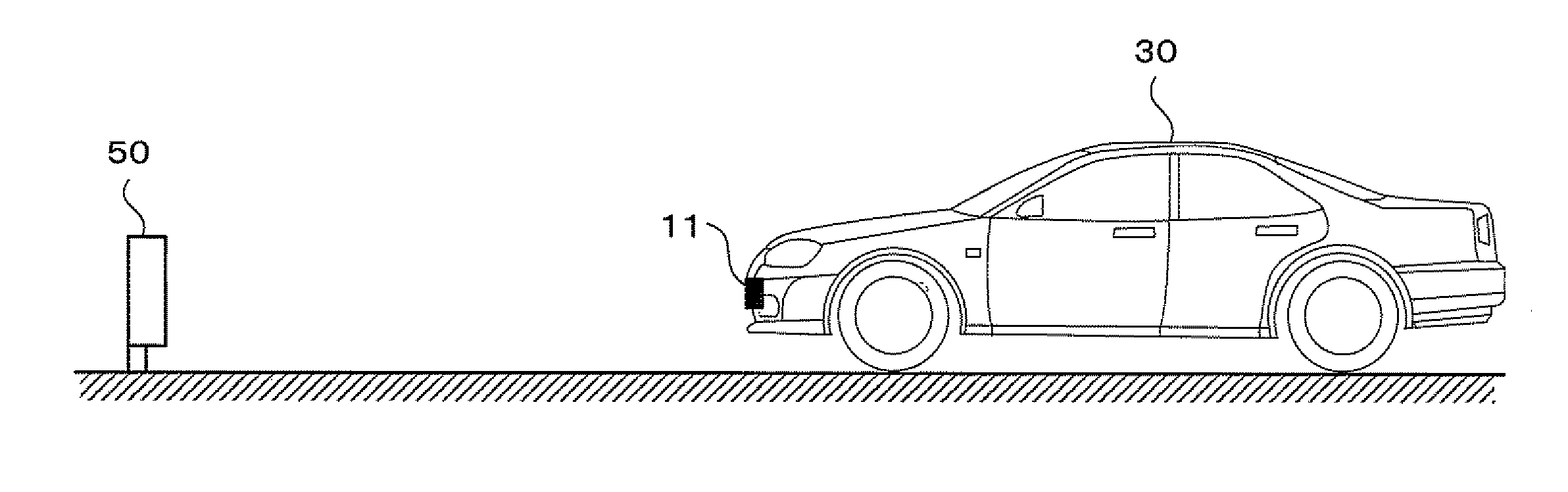
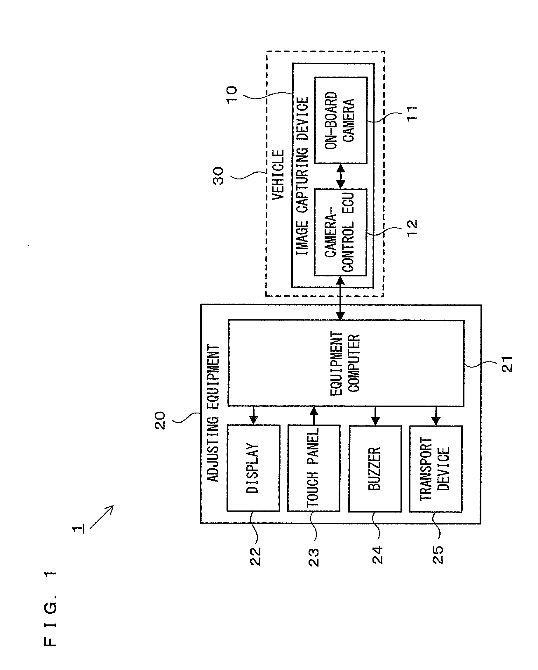
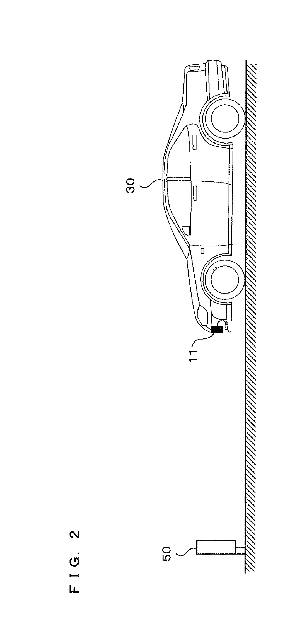
[0038]First, with reference to FIG. 1, a configuration of the optical axis adjusting system 1 will be described. FIG. 1 is a block diagram showing the configuration of the optical axis adjusting system 1 according to the first embodiment. As shown in FIG. 1, the optical axis adjusting system 1 includes an image capturing device 10 and adjusting equipment 20. The image capturing device 10 includes an on-board camera 11 and a camera-control ECU 12. In addition, the adjusting equipment 20 includes an equipment computer 21, a liquid crystal display 22, a touch panel 23, a buzzer 24, and a transport device 25. Described in the following is an example in which the image capturing device 10 is mounted on a vehicle 30.

[0039]The on-board camera 1...

second embodiment

[0068

[0069]In the first embodiment, an example has been described in which the adjustment setting value TA is stored and changed by the adjusting equipment 20. However, the value of the adjustment setting value TA may be stored and changeable by a device mounted on the vehicle 30. In the following, an image capturing device 40 according to a second embodiment will be described.

[0070]As shown in FIG. 7, the image capturing device 40 according to the second embodiment includes an on-board camera 60, a camera-control ECU 61, a display 62, a touch panel 63, and a buzzer 64. FIG. 7 is a block diagram showing a configuration of the image capturing device according to the second embodiment. It should be noted that the image capturing device 40 is mounted on the vehicle 30.

[0071]The on-board camera 60, the camera-control ECU 61, the display 62, the touch panel 63, and the buzzer 64 are devices similar to the display 22, the touch panel 23, and the buzzer 24 according to the first embodiment...


PUM


Abstract

Provided is an image capturing device.
The image capturing device includes: a parameter setting section that automatically sets, (A) during ordinary times, a setting parameter for image-capturing to a value that depends on brightness of an image-capturing environment, and that sets, (B) at a time of the adjusting of the optical axis, the setting parameter to a predetermined adjustment setting value; a setting value receiving section that receives the adjustment setting value from the adjusting device when the adjusting of the optical axis is initiated; and an optical axis adjusting section that adjusts the optical axis based on an image captured in a state where the setting parameter is set to be the adjustment setting value. The adjusting device includes: a setting value storing section that stores the adjustment setting value in advance; and a setting value transmitting section that transmits the adjustment setting value to the image capturing device.

Description

TECHNICAL FIELD[0001]The present invention relates to an image capturing device, an adjusting device, and an optical axis adjusting system for the image capturing device; and more specifically, relates to an image capturing device, an adjusting device, and an optical axis adjusting system for the image capturing device for adjusting an optical axis based on a captured image of a target.BACKGROUND ART[0002]In recent years, there are vehicles having mounted thereon cameras for acquiring images of the peripheries of the vehicles. The cameras are mounted for acquiring images of the forward direction of the vehicles so as to be used, for example, for traffic lane recognition, preceding vehicle recognition, and the like. When attaching such a camera to a vehicle, misalignment of an optical axis direction occurs with respect to the traveling direction of the vehicle when attaching the camera due to mechanical factors and control-technological factors. A misalignment in the optical axis dir...

Claims


Application Information

Patent Timeline
Patent Type & Authority Applications(United States)
IPC IPC(8): H04N7/18
CPCH04N5/232H04N5/23216H04N5/2351H04N23/60H04N23/62H04N23/71
Inventor USAMI, MASAYUKIKAGEYAMA, SHIOYAKOJIMA, KEIGO
Owner TOYOTA JIDOSHA KK
Why Eureka
Try Eureka