
Image capturing apparatus and control method therefor

a technology of image capture apparatus and control method, which is applied in the direction of color television details, television system details, television systems, etc., can solve the problems of increasing noise, and reducing the image quality of the image, so as to reduce the degradation of the image quality

Inactive Publication Date: 2012-08-23
CANON KK
View PDF7 Cites 29 Cited by
  • Summary
  • Abstract
  • Description
  • Claims
  • Application Information

AI Technical Summary

Benefits of technology

[0009]The present invention has been achieved in light of such circumstances, and provides a technique for suppressing degradation in image quality when changing the image-capturing frame rate of video.
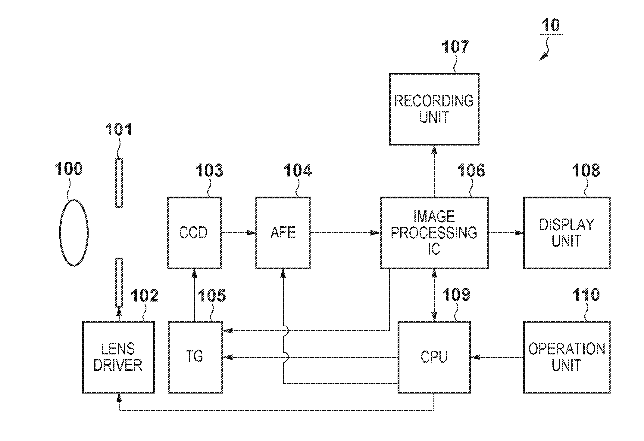
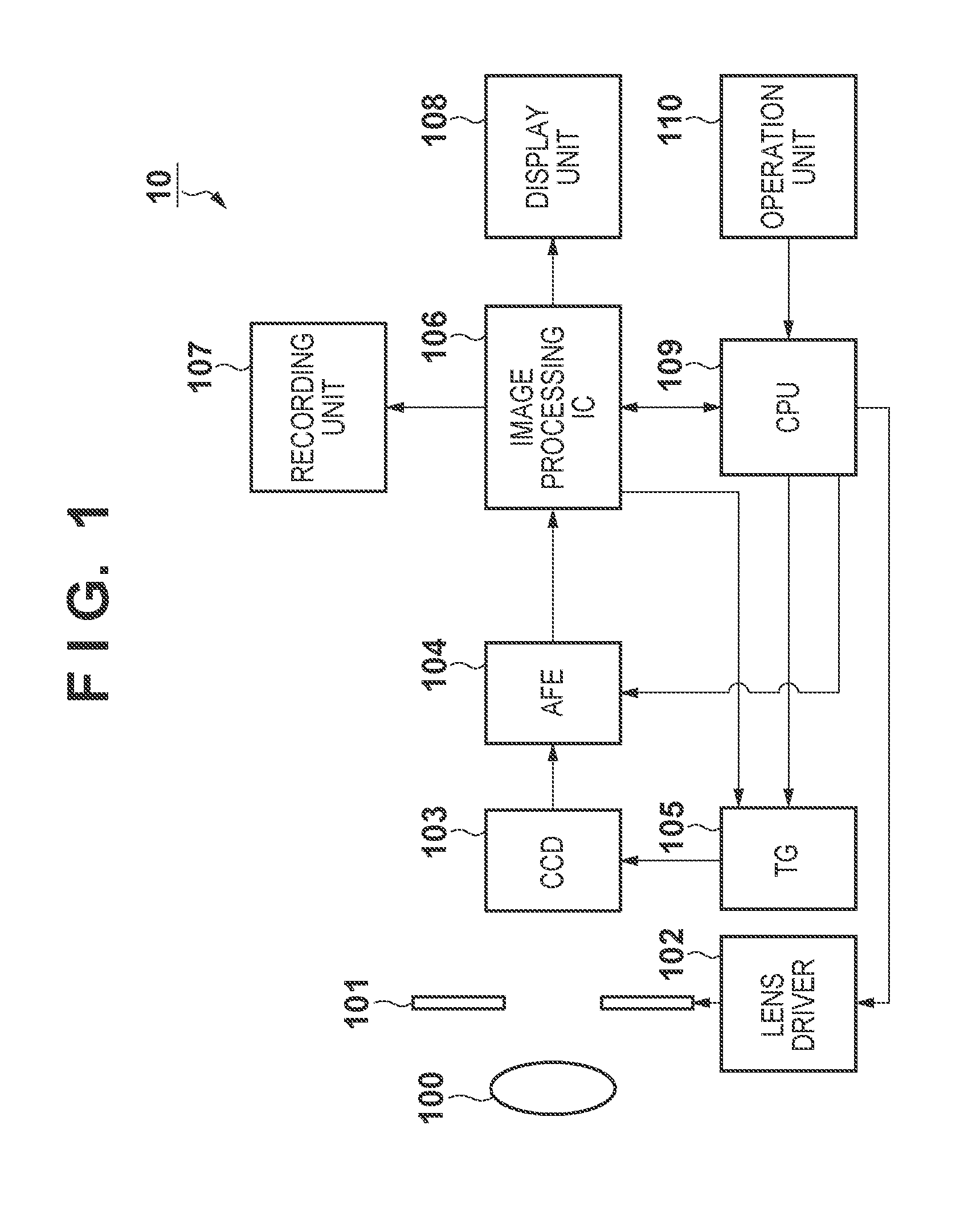
[0011]According to a second aspect of the present invention, there is provided an image capturing apparatus, comprising: an image capturing unit configured to acquire video data by reading out an image signal from an image sensing element at a first frame rate or a second frame rate higher than the first frame rate, the image sensing element generating the image signal by photoelectric conversion of light incident from an optical system including an aperture; a control unit configured to perform control of the aperture and an exposure time of the image sensing element within a range in which the exposure time is shorter than or equal to a maximum exposure time that is a reciprocal of a frame rate of the image capturing unit, so that luminance of the image signal acquired by the image capturing unit is at a predetermined level; and a reception unit configured to receive a switching instruction to switch the frame rate of the image capturing unit from the first frame rate to the second frame rate, wherein in a case where the switching instruction is received when the exposure time is longer than a maximum exposure time corresponding to the second frame rate, the control unit performs control for opening the aperture so as to compensate for a drop in the luminance of the image signal as a result of shortening the exposure time to the maximum exposure time corresponding to the second frame rate, and also performs control for switching the frame rate of the image capturing unit from the first frame rate to the second frame rate, and in the switching control, the control unit gradually changes the frame rate of the image capturing unit from the first frame rate to the second frame rate while the aperture is being gradually opened by the opening control.
[0014]With the above-described configuration, the present invention enables suppression of degradation in image quality when changing the image-capturing frame rate of video.

Problems solved by technology

However, a certain amount of time is required for the aperture to be changed into the target state.
Furthermore, an increase in gain results in an increase in noise and degradation in image quality.

Method used


Image

  • Image capturing apparatus and control method therefor
  • Image capturing apparatus and control method therefor
  • Image capturing apparatus and control method therefor

Examples


first embodiment

[0045]As described previously, when the image-capturing frame rate changes from “Normal” to “High Speed”, video may be darkened as a result of the shortened exposure time. In the case where a drop in luminance is compensated for by opening the aperture 101, a certain amount of time is required to obtain video with appropriate luminance because the aperture 101 requires a certain amount of time to be changed to the target state. In view of this, in a first embodiment, the DVC 10 suppresses degradation in image quality when changing the image-capturing frame rate of video by modifying part of the program diagram as indicated by the dashed dotted line in FIG. 3.

[0046]In the first embodiment, the normal frame rate is assumed to be 60 fps and the high frame rate is assumed to be 240 fps, but the respective frame rates are not limited thereto.

[0047]In FIG. 3, the shutter speed (that is, exposure time) at the border between the range E and the range F is 1 / 240 seconds, which is shorter tha...

second embodiment

[0056]A second embodiment first describes a configuration for suppressing an increase in gain during image capturing performed at the normal frame rate, and then describes a configuration for frame-cyclic noise reduction. In the second embodiment, the basic configuration of the DVC 10 is similar to that of the first embodiment (see FIG. 1), but the program diagram shown in FIG. 3 is modified into the one shown in FIG. 5. In the second embodiment as well, the normal frame rate is assumed to be 60 fps and the high frame rate is assumed to be 240 fps.

[0057]A comparison of FIG. 3 and FIG. 5 shows the difference therebetween in that the range G in FIG. 3 is divided into ranges G1 and G2 in FIG. 5. In the range G1, the shutter speed is reduced from 1 / 240 seconds to 1 / 60 seconds as the subject gets darker. The F number and the gain do not change during this time. If the subject gets even darker, the gain is increased while fixing the shutter speed and the F number as shown in the range G2....

third embodiment

[0068]In the first and second embodiments, the DVC 10 suppresses degradation in image quality when changing the image-capturing frame rate by, in principle, limiting the exposure time since before the image-capturing frame rate changes to “High Speed”. In contrast, in a third embodiment, the DVC 10 suppresses degradation in image quality by taking measures at the time when the image-capturing frame rate changes from “Normal” to “High Speed”. In the third embodiment, the basic configuration of the DVC 10 is similar to that of the first embodiment (see FIG. 1), but the program diagram to be used is the portion indicated by the solid line in FIG. 3, rather than the portion indicated by the dashed dotted line. In the third embodiment as well, the normal frame rate is assumed to be 60 fps and the high frame rate is assumed to be 240 fps.

[0069]As described previously, examples of the time when the image-capturing frame rate changes from “Normal” to “High Speed” include the time when video...


PUM


Abstract

There is provided an image capturing apparatus, comprising an image capturing unit configured to acquire video data at a first frame rate or a second frame rate higher than the first frame rate; and a control unit configured to perform control of an aperture and an exposure time within a range in which the exposure time is shorter than or equal to a maximum exposure time that is a reciprocal of a frame rate of the image capturing unit, so that luminance of the image signal acquired by the image capturing unit is at a predetermined level, wherein when the image capturing unit is operating at the first frame rate, the control unit performs the control within a range in which the exposure time is shorter than a first time that is a reciprocal of the first frame rate.

Description

BACKGROUND OF THE INVENTION[0001]1. Field of the Invention[0002]The present invention relates to an image capturing apparatus and a control method therefor.[0003]2. Description of the Related Art[0004]Image capturing apparatuses such as video cameras include those that can change the frame rate when capturing images of subjects (hereinafter referred to as the “image-capturing frame rate”). Using such an image capturing apparatus, video data that has been captured and recorded at an image-capturing frame rate (e.g., 240 fps) higher than a normal image-capturing frame rate (e.g., 60 fps) can be reproduced at the normal frame rate. Such reproduction makes it possible to obtain slow playback video in which a subject motion is slower than actual motion.[0005]The frame rate of a liquid crystal display of such an image capturing apparatus is generally equivalent to the normal image-capturing frame rate (e.g., 60 fps). Thus, in the case where the liquid crystal display is used as an electro...

Claims


Application Information

Patent Timeline
IPC IPC(8): H04N5/238
CPCH04N5/2353H04N5/238H04N23/73H04N23/75
Inventor TAKITA, TARO
Owner CANON KK
Learn More