Device for assisting in the underwater extraction or insertion of an elongate element disposed in a pipe, and method for assisting in the extraction or insertion of one such element

a technology of elongate elements and underwater extraction, which is applied in the direction of greenhouse gas reduction, nuclear elements, nuclear engineering, etc., can solve the problems of not being able to have a reliable and representative image of the actual temperature of the coolant of the core of the reactor, unable to achieve the effect of reducing the number of elongate elements, so as to facilitate the extraction or insertion of elonga

Inactive Publication Date: 2012-08-23
AREVA NP SAS
View PDF7 Cites 13 Cited by
  • Summary
  • Abstract
  • Description
  • Claims
  • Application Information

AI Technical Summary

Benefits of technology

[0024]An object of the invention is to provide a device and method for assisting in the extraction or insertion of an elongate element disposed in a pipe that makes it possible, through easy-to-use means, to avoid these drawbacks and facilitate the extraction or insertion of the elongate element.

Problems solved by technology

The thermocouples introduced into the pipes are subject to high temperature and pressure stresses, with the result that some of them may have operating defects after a certain residence time in the vat of the reactor.
Thus, it is no longer possible to have a reliable and representative image of the actual temperature of the coolant of the core of the reactor.
In fact, because the thermocouple is mounted with very little, and even practically no play in certain parts of the pipes, the frictional forces, during removal of the thermocouples, can be very significant.
In certain cases, the thermocouple is blocked in the pipe and cannot be removed by pulling without risk of rupture.
In this case, the measuring pipe is lost, which causes the loss of a measuring point.
In other cases, despite successful pulling, it can be difficult or even impossible to introduce a new thermocouple into the pipe.
Lastly, simple pulling on the thermocouple can lead to damage to the wall of the corresponding pipe, which is detrimental to the insertion of a new thermocouple.
However, in the case of thermocouples whereof the blocking part is situated in the lower end of the pipe, i.e. at a significant distance from the thermocouple on which the pulling is exerted and through which the ultrasounds are transmitted, this known method is ineffective.

Method used


Image

  • Device for assisting in the underwater extraction or insertion of an elongate element disposed in a pipe, and method for assisting in the extraction or insertion of one such element
  • Device for assisting in the underwater extraction or insertion of an elongate element disposed in a pipe, and method for assisting in the extraction or insertion of one such element
  • Device for assisting in the underwater extraction or insertion of an elongate element disposed in a pipe, and method for assisting in the extraction or insertion of one such element

Examples


Embodiment Construction

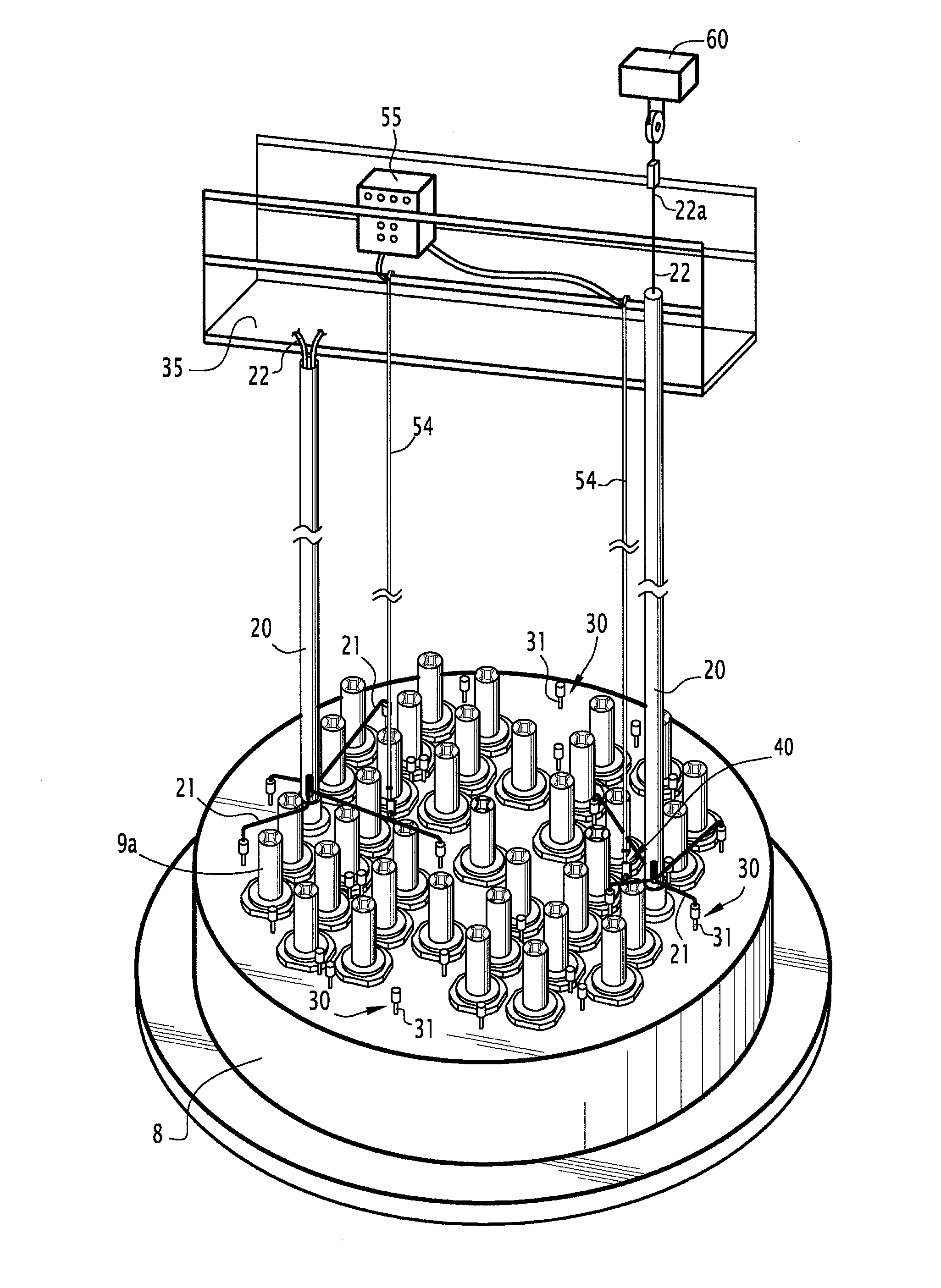
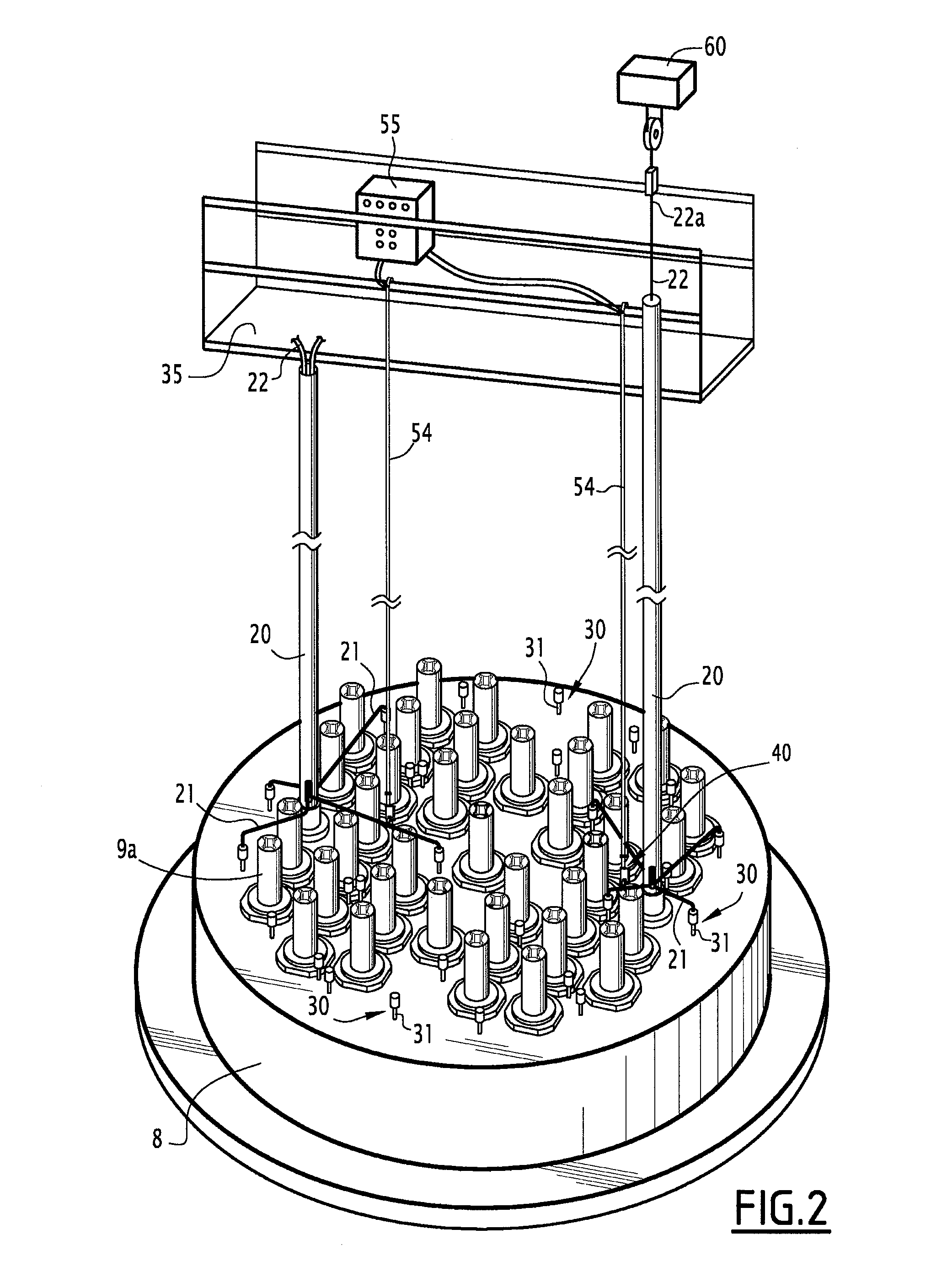
[0056]In the following description, the device according to embodiments of the invention will be described to assist in the extraction or insertion of an elongate element formed by a thermocouple disposed in a measuring pipe of the upper internal equipment of a pressurized water nuclear reactor.

[0057]This device can be used to assist with the extraction or insertion of any other elongate element in a pipe.

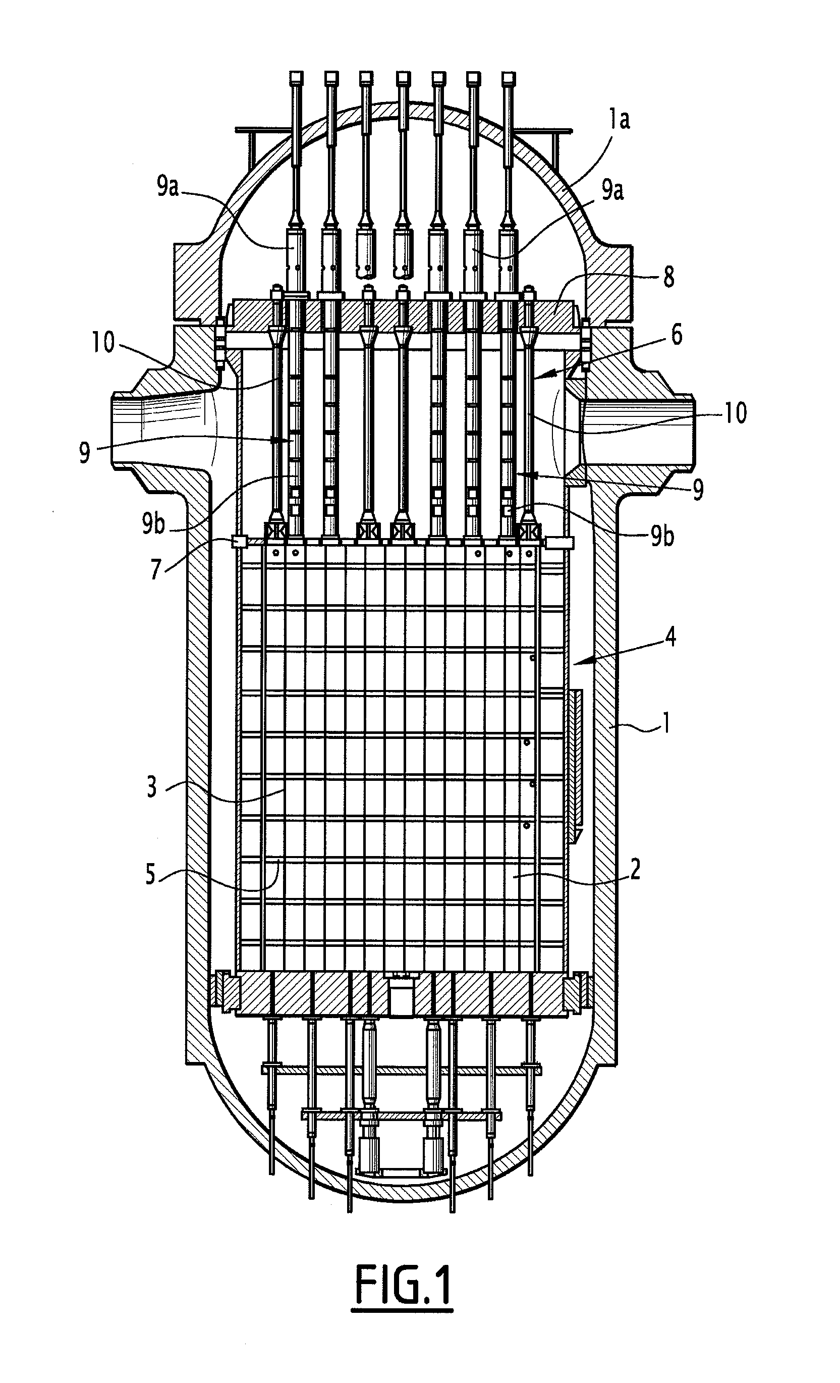
[0058]FIG. 1 diagrammatically illustrates a vat of a pressurized water nuclear reactor designated by reference 1. Traditionally, disposed inside the vat 1 of the nuclear reactor is the core 2 formed by fuel assemblies 3 juxtaposed so that the longitudinal axis of the fuel assemblies is vertical. The core 2 of the reactor is disposed inside lower internal equipment designated by general reference 4 and in particular comprising the partition 5 of the core.

[0059]The nuclear reactor also comprises upper internal equipment designated by general reference 6 that rests on the upper plate ...


PUM


Abstract

A device for assisting in the underwater extraction or insertion of an elongate element disposed in a pipe is provided. The device includes a clamping and vibration-generating assembly including a sealed housing bearing a gripper and including a member for tightening the gripper on the pipe, an adjustable vibrator for vibrating the housing and the gripper, and a member for measuring the vibration produced by the vibrator on the pipe in order to determine the optimum vibration The device also includes a controller for remotely controlling the gripper and the vibrator. A method for assisting in the extraction or insertion of an elongate element is also provided.

Description

[0001]The present invention relates to a device for assisting in the underwater extraction or insertion of an elongate element disposed in a pipe, and in particular a thermocouple disposed in a measuring pipe for the upper internal equipment of a pressurized water nuclear reactor.[0002]The invention also relates to a method for assisting in the underwater extraction or insertion of an elongate element disposed in a pipe.BACKGROUND[0003]Pressurized water nuclear reactors comprise, inside a vat, the core of the nuclear reactor made up of fuel assemblies having a prismatic shape with their vertical axis and, above the core, upper internal equipment in particular comprising a set of vertical guide-tubes making it possible to ensure the guiding of the control rods formed by bundles of rods placed parallel to one another and containing a material absorbing neutrons.[0004]To control the reactors by adjusting the reactivity of the core, the clusters of absorber rods are moved in the vertica...

Claims


Application Information

Patent Timeline
Patent Type & Authority Applications(United States)
IPC IPC(8): G21C19/105G21C17/00
CPCG21C19/105G21C17/112G21C19/20G21C19/207Y02E30/30
Inventor LANGE, FREDERICFLOQUET, JACQUESMURAT, GERARD
Owner AREVA NP SAS
Why Eureka
Try Eureka