Robotic Palletizer Cell And Method Of Construction

a robot and palletizer technology, applied in the field of robot palletizer cells, can solve the problems of lack of adaptability to particular applications, lack of flexibility, and inability to be configured differently

Inactive Publication Date: 2012-08-23
ROBERTS BRIAN THOMAS
View PDF29 Cites 18 Cited by
  • Summary
  • Abstract
  • Description
  • Claims
  • Application Information

AI Technical Summary

Benefits of technology

[0008]It is an object of the present invention to provide modular equipment and a method for creating pelletizing cells which make, designing, building and installing such cells much quicker and cheaper than previously possible by reducing the need for independently locating each item of equipment in the installation process.

Problems solved by technology

The result of this approach is that the time required to design, build and install a palletizer cell is considerable, and the cost relatively high.
While some attempts have been made to build standardized elements of the equipment needed, these have been lacking in their ability to be adapted to particular applications and to be configured differently for those applications, and in any event each element needed to be set up in the field in an appropriate position.

Method used


Image

  • Robotic Palletizer Cell And Method Of Construction
  • Robotic Palletizer Cell And Method Of Construction
  • Robotic Palletizer Cell And Method Of Construction

Examples


Embodiment Construction

[0031]In the following detailed description, certain specific terminology will be employed for the sake of clarity and a particular embodiment described in accordance with the requirements of 35 USC 112, but it is to be understood that the same is not intended to be limiting and should not be so construed inasmuch as the invention is capable of taking many forms and variations within the scope of the appended claims.

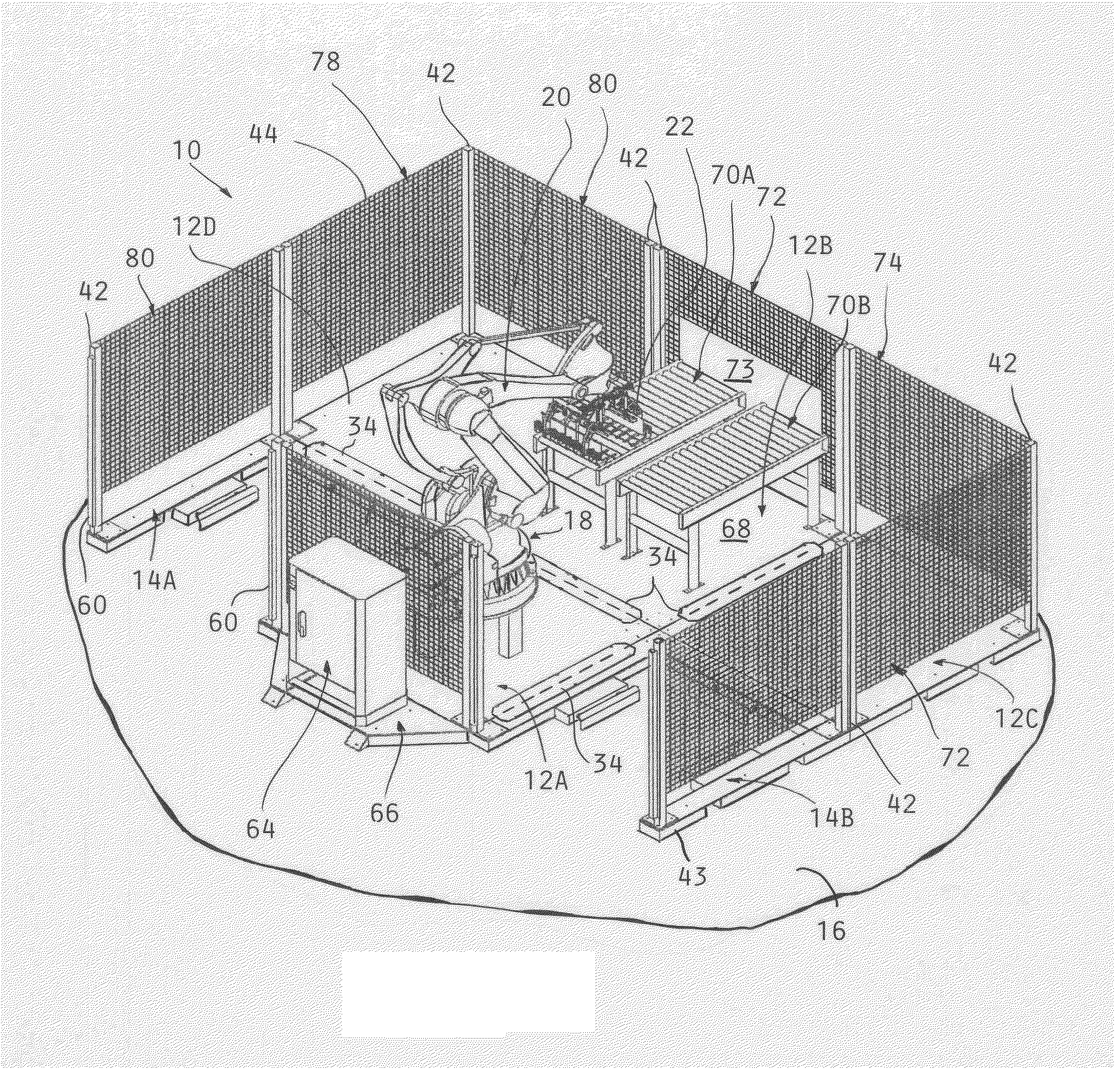
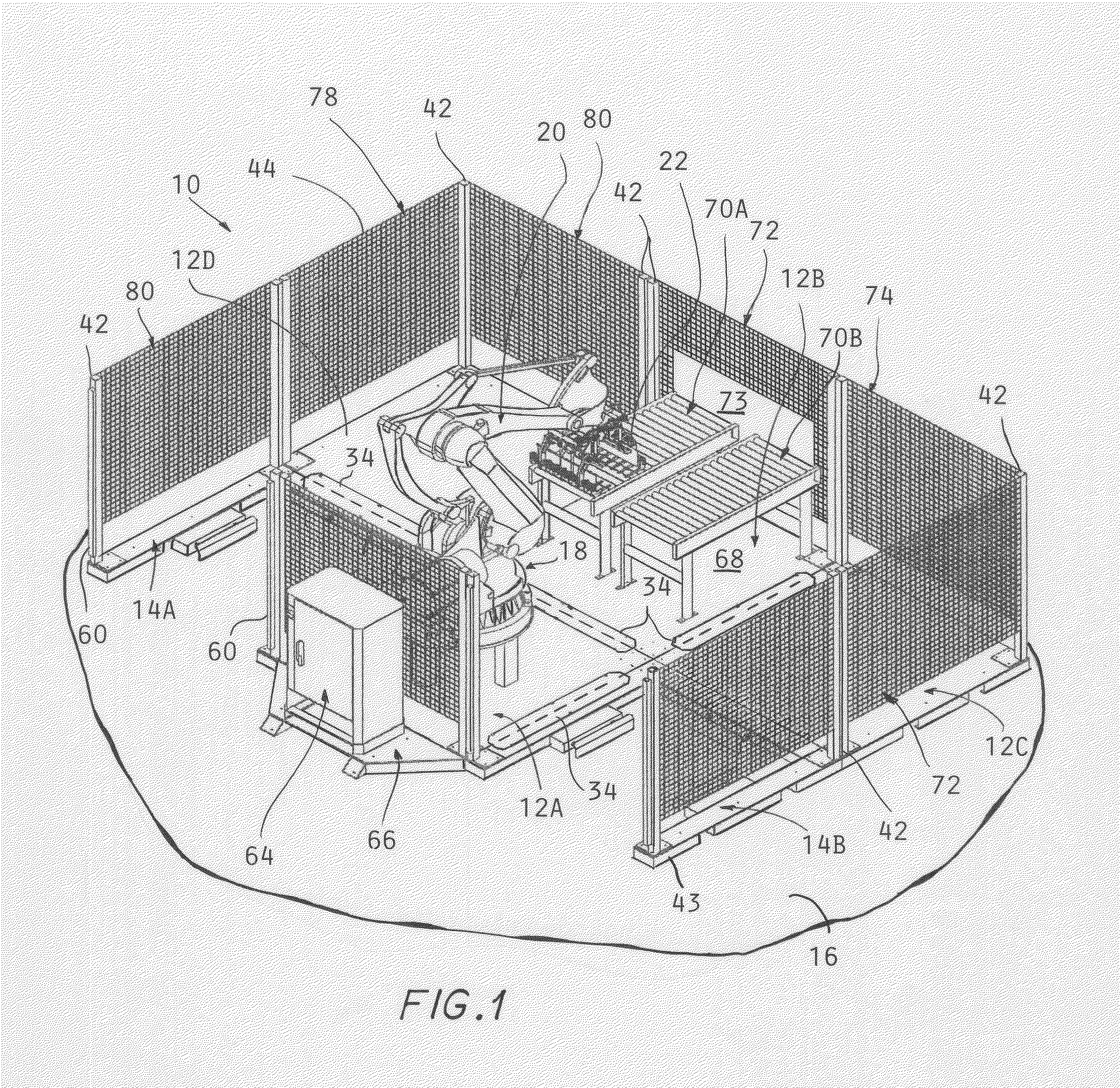
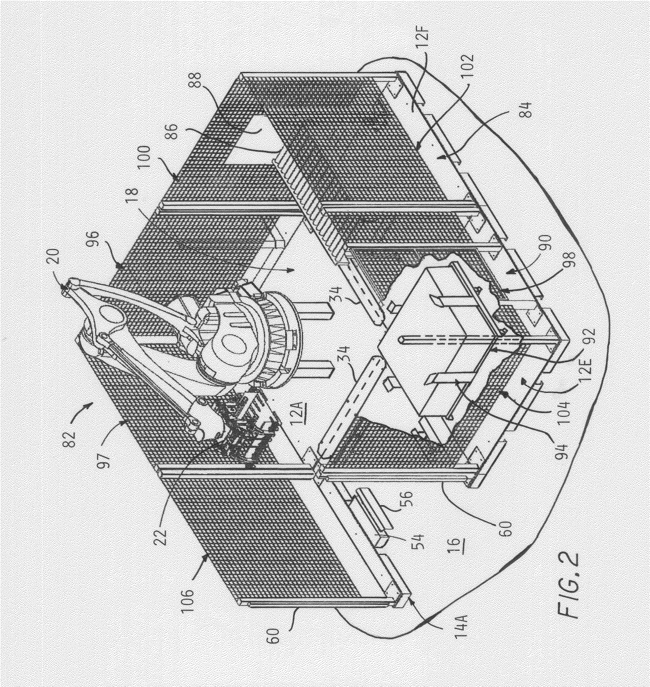
[0032]Referring to the drawings, and particularly FIG. 1, a palletizer cell 10 is shown, constructed using components according to the present invention. This includes a plurality of rectangular, preferably square, platform bases of two different types, i.e., four solid square platform bases 12A, 12B, 12C, and 12D, and two platform bases 14A, 14B of an overall square configuration but having an opening extending in from one side to create a general U-shape.

[0033]All of the platform bases 12A-12D and 14A, 14B rest on the factory floor 16, held together in contact with one...


PUM


Abstract

A method of constructing a palletizer cell by providing square platform bases which are assembled into an array in abutment with each other, each platform base mounting a respective component of palletizing equipment, such as a robot, one or more conveyors, a slip sheet bin, a discharge module, etc. with one platform base anchored to the factory floor and the rest attached to one or another of the platform bases to form the array of platform bases thereby properly locating the various equipment with each other by the fitting together of the platform bases. Safety fencing sections are mounted atop one or more outer sides to substantially enclose the space within the palletizer cell. Each platform base is formed with side openings which may be engaged with the tines of a fork lift.

Description

CROSS REFERENCE TO RELATED APPLICATIONS[0001]This application claims the benefit of U.S. provisional application No. 61 / 444,507 filed on Feb. 18, 2011, incorporated herein by reference.BACKGROUND OF THE INVENTION[0002]This invention concerns robotic palletizing cells, in which items are stacked by robots. Palletizing has in the past traditionally mostly been done by dedicated automation equipment.[0003]In more recent years, robotic palletizing in which a robot carries out stacking of product has become more common for some applications, due to increased flexibility in layout, configuration, and pallet pattern creation and in running multiple lines.[0004]Robotic palletizing involves custom designing the layout of the various pieces of equipment, such as the robot, conveyors, pallet stacks, etc., and then locating each piece of the equipment on the factory floor in the proper position and separately anchoring each piece of equipment to the factory floor, and running wires in the field...

Claims


Application Information

Patent Timeline
Patent Type & Authority Applications(United States)
IPC IPC(8): B65G57/00E04B1/00
CPCB65G61/00E04B2/7433B65G57/03
Inventor ROBERTS, BRIAN THOMAS
Owner ROBERTS BRIAN THOMAS
Why Eureka
Try Eureka