Radio base station, user terminal and frequency band sharing method

a technology of user terminal and radio base station, which is applied in the direction of synchronisation arrangement, network traffic/resource management, electrical apparatus, etc., can solve the problems of increasing the implementing load of the user terminal of the first radio communication system, and the user terminal receives considerable interference so as to increase the implementing load of the user terminal and reduce the interference received from the radio base station

Active Publication Date: 2012-08-23
NTT DOCOMO INC
View PDF2 Cites 38 Cited by
  • Summary
  • Abstract
  • Description
  • Claims
  • Application Information

AI Technical Summary

Benefits of technology

[0008]The present invention has been implemented in view of the above problem and it is an object of the present invention to provide a radio base station, user terminal and frequency band sharing method when communication areas of a plurality of radio communication systems sharing a frequency band overlap each other, without considerably increasing the implementing load of a user terminal of a first radio communication system, allowing the user terminal of the first radio communication system to reduce interference received from a radio base station of a second radio communication system.

Problems solved by technology

When communication areas of a plurality of radio communication systems sharing a frequency band overlap each other, if a user terminal of a first radio communication system (e.g., MCS) is located near a radio base station of a second radio communication system (e.g., CRS), the user terminal receives considerable interference from the radio base station.
However, when communication areas of a plurality of radio communication systems sharing a frequency band overlap each other, as described above, if the user terminal of the first radio communication system (e.g., MCS) implements functions for enabling to detect a broadcast signal from the radio base station of the second radio communication system (e.g., CRS) and request the radio base station to perform interference reduction processing, there is a problem that the implementing load of the user terminal of the first radio communication system increases.

Method used


Image

  • Radio base station, user terminal and frequency band sharing method
  • Radio base station, user terminal and frequency band sharing method
  • Radio base station, user terminal and frequency band sharing method

Examples


Embodiment Construction

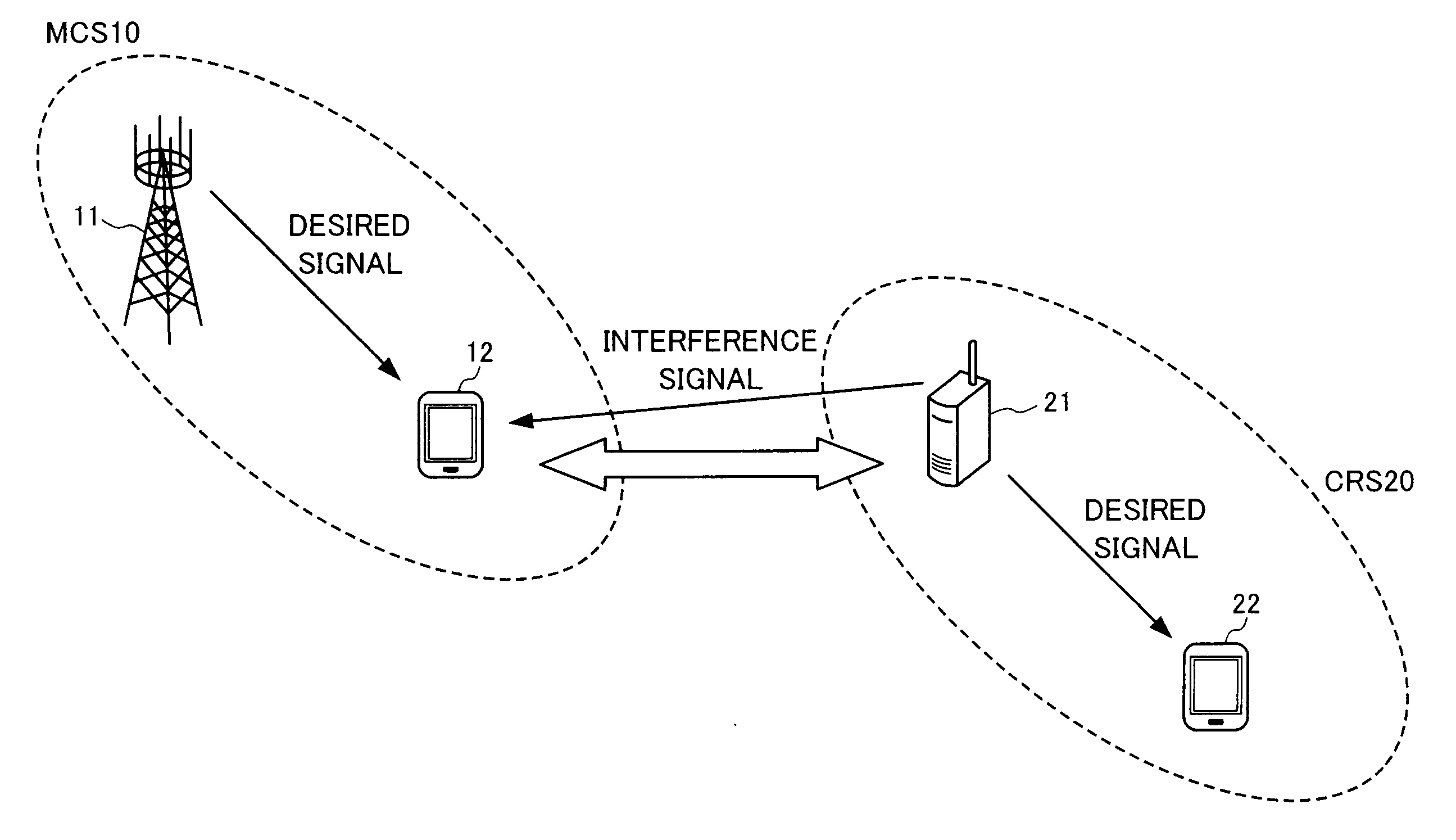
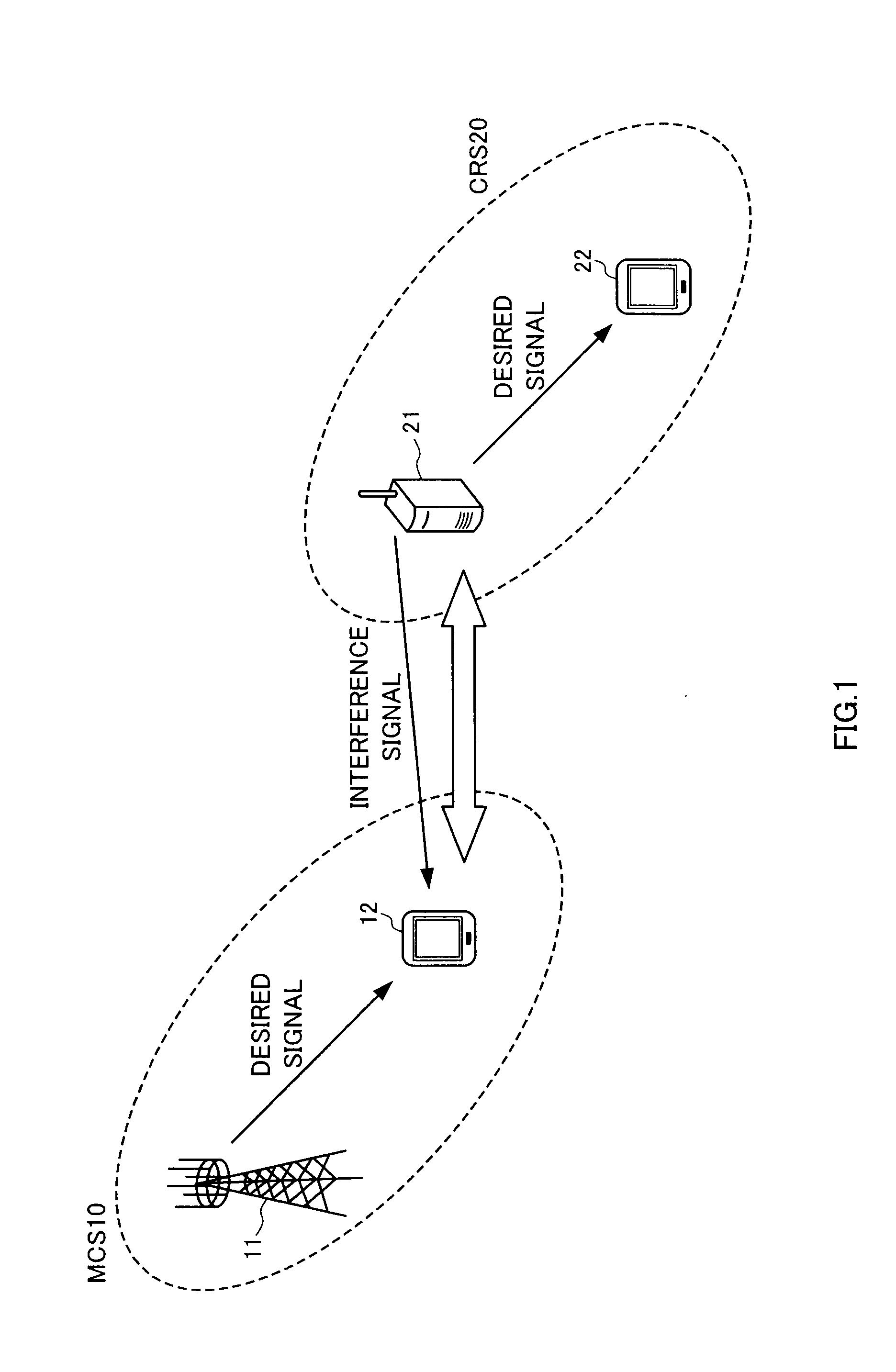
[0020]FIG. 1 is a diagram illustrating a system configuration when communication areas of a plurality of radio communication systems sharing a frequency band overlap. The system configuration shown in FIG. 1 is an illustration and is not limited to this configuration. The present invention is applicable to any configuration in which a plurality of radio communication areas sharing the same frequency band are arranged so as to overlap each other.

[0021]An example will be described below where an MCS (Macro Cell System) 10 and a CRS (Cognitive Radio System) 20 share a frequency band, but a plurality of radio communication systems sharing a frequency band are not limited to this. The present invention is applicable to any combination of a plurality of radio communication systems sharing at least part of a frequency band.

[0022]FIG. 1 shows a case where MCS 10 which is an existing system and CRS 20 have overlapping communication areas each other and share a frequency band. A radio base st...


PUM


Abstract

A CRS base station (21) includes a transmitting section configured to transmit a synchronization establishment signal, a receiving section configured to receive a random access signal corresponding to the synchronization establishment signal, a determining section configured to determine whether or not the random access signal received by the receiving section has been transmitted from an MCS terminal (12) and an interference reduction processing section configured to perform interference reduction processing on the MCS terminal (12) when the determining section determines that the random access signal has been transmitted from the MCS terminal (12).

Description

CROSS-REFERENCE TO RELATED APPLICATIONS[0001]This application is based upon and claims the benefit of priority from the prior Japanese Patent Application No. 2011-037068 filed on Feb. 23, 2011; the entire contents of which are incorporated herein by reference.BACKGROUND OF THE INVENTION[0002]1. Field of the Invention[0003]The present invention relates to a radio base station, user terminal and frequency band sharing method for sharing at least part of a frequency band between radio communication systems whose communication areas spatially and at least partially overlap each other.[0004]2. Description of the Related Art[0005]In recent years, studies are being carried out on a system configuration in which in a communication area of MCS (Macro Cell System) which is an existing radio communication system, a communication area of CRS (Cognitive Radio System) different from the MCS is arranged so as to overlap with the communication area of the MCS. In such a system configuration of comm...

Claims


Application Information

Patent Timeline
Patent Type & Authority Applications(United States)
IPC IPC(8): H04W56/00H04W72/04H04W88/08H04W74/08H04W88/02
CPCH04B1/005H04B1/1027H04W16/14H04W72/082H04W56/00H04W74/0833H04W88/08H04W28/048H04W28/04H04W72/541
Inventor FUJII, HIROMASAYASUDA, HIROTOHARADA, HIROKIMIURA, SHUNJIKAYAMA, HIDETOSHI
Owner NTT DOCOMO INC
Why Eureka
Try Eureka